Plastically deformable coil energy absorber systems

a technology of energy absorber and coil, which is applied in the direction of elastic dampers, bumpers, vehicular safety arrangments, etc., can solve the problems of high displacement, inability to fully absorb energy, so as to reduce or simplify vehicle repairs, the effect of mass reduction

Inactive Publication Date: 2012-08-09
SABIC GLOBAL TECH BV
View PDF55 Cites 5 Cited by
  • Summary
  • Abstract
  • Description
  • Claims
  • Application Information

AI Technical Summary

Problems solved by technology

Foam based systems typically have slow loading upon impact resulting in a high displacement.
Further, while foams are effective to a sixty or seventy percent compression, beyond that point foams become incompressible such that the impact energy is not fully absorbed.
Typically, as temperature is lowered, the foam becomes more rigid, resulting in higher loads to attain displacement.
Conversely, as temperature rises, foams become more compliant resulting in higher displacements and possible vehicle damage.
Some of them require significant structural modifications to the headlamp which increase its volume, weight, and / or cost.
In the current competitive automotive market, a major challenge for a design engineer is to reduce component mass, thus reducing the system cost and increasing the fuel efficiency.
At present, original equipment manufacturers (OEMs) are very aggressive regarding lower energy absorber mass as the available alternative system provides low cost and low mass solution but with a compromise in performance.

Method used


Image

  • Plastically deformable coil energy absorber systems
  • Plastically deformable coil energy absorber systems
  • Plastically deformable coil energy absorber systems

Examples


example 1

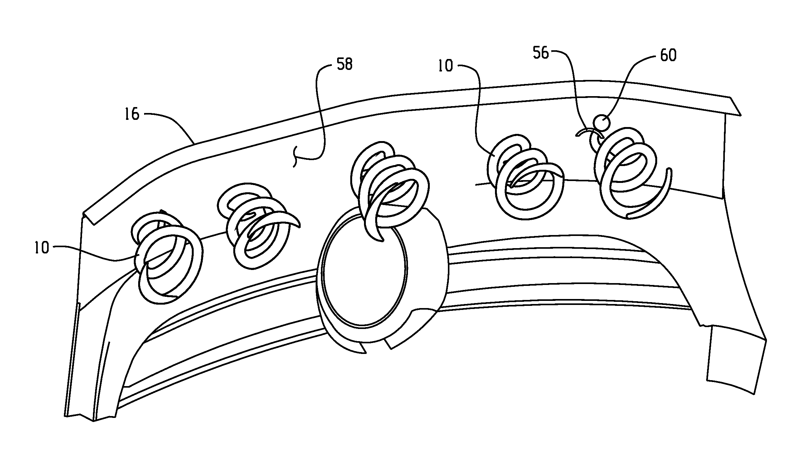
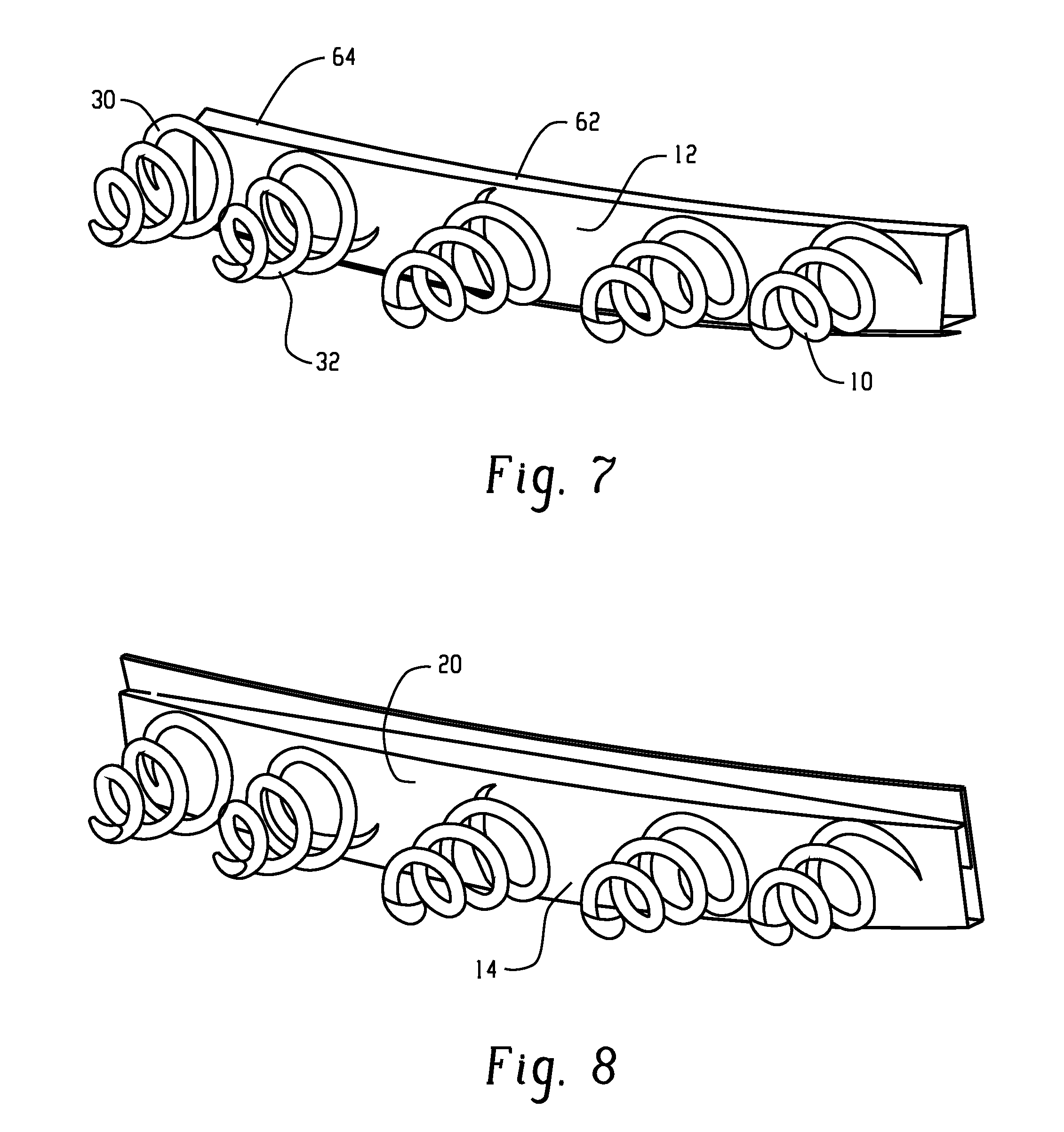
[0069]Example 1 is an energy absorber design comprising conical, helical, plastic springs disposed across a steel bumper beam as illustrated in FIG. 7. The springs had a diameter at their base of 80 mm, a diameter at the top of 25 mm, a coil diameter of 15 mm, and a depth (e.g., height from the base to the top) of 80 mm. The springs were formed from a blend of polycarbonate and polybutylene terephthalate (e.g., XENOY® commercially available from SABIC Innovative Plastics).

TABLE 1G-Rota-Max.BendingExam-ImpactMassloadtionSheerForceMovementples(at Y = 0)(kg)(g)(deg.)(mm)(kN)(N · m)Comp.Lower Leg2.0110.62.24.8——Ex. 1Ex. 1Lower Leg1.594.81.7——Comp.Upper Leg2.0———6.84333.9Ex. 1Ex. 1Upper Leg1.5———4.87268.2

[0070]The results comparing the thermoplastic energy absorber (Comp. Ex. 1) to the plastic spring design (Ex. 1) are set forth in Table 1. As is clear from Table 1, the use of the helical spring enabled, for the upper leg, a reduction in bending movement of greater than 50 Newton-meters ...

example 2

[0072]Prototype samples were prepared to validate the CAE studies. From these prototypes, component level tests were conducted. Commercially available polypropylene material was used to develop prototype samples. The polypropylene rods were heated below the melt temperature, and winded over a wooden mandrel manually to form helical conical coils. A compression test was performed in a Universal testing Machine (UTM) and a force versus deformation curve was compared with the CAE studies of compression phenomenon in Example 1 and Comparative Example 1 utilizing the same parameters. FIG. 15 displays a descent correlation between the CAE examples, line 92 (Comparative Example 1 and Example 1) and Example 2, line 90. A simple compression test was performed for developed coils using a UTM. One end of the coil was fixed with the help of jaws, and the coil was compress at the free end by a steel plate moving with a speed of 6 millimeters per minute (mm / min.). The same test procedure was repl...


PUM


Abstract

In one embodiment, an energy management system can comprise: a vehicle energy management system comprises: a support structure selected from a bumper beam, a body in white, a body in black, a front-end module, a radiator support beam, a bumper support bracket, a component projecting from the body in white, a component projecting from the body in black, and combinations comprising at least one of the foregoing; a covering; and a coil energy absorber made of plastic. The coil energy absorber has an initial height and is located between the support structure and the covering. The coil energy absorber absorbs energy upon impact such that, after the impact, the coil energy absorber has a final height that is less than or equal to 90% of the initial height.

Description

CROSS REFERENCE TO RELATED APPLICATIONS[0001]This application is a continuation of U.S. patent application Ser. No. 12 / 724,962, filed on Mar. 16, 2010, which is herein incorporated by reference in its entirety.BACKGROUND[0002]This disclosure relates to energy management systems for pedestrian safety and vehicle damageability, and especially relates to energy absorber systems that employ plastic deformation.[0003]Increased importance has been placed on methods for minimizing the amount of injury suffered by a pedestrian when struck by a vehicle. Focus has been on bumper assemblies, headlamps. For bumper assemblies, foam resins have been used for energy absorption. Foam based systems typically have slow loading upon impact resulting in a high displacement. Further, while foams are effective to a sixty or seventy percent compression, beyond that point foams become incompressible such that the impact energy is not fully absorbed. The remaining impact energy is absorbed through deformati...

Claims


Application Information

Patent Timeline
Patent Type & Authority Applications(United States)
IPC IPC(8): B60R19/28
CPCB60R19/18B60R2019/186F16F7/12F16F1/04B60R2019/1893
Inventor NAGWANSHI, DHANENDRA KUMARMARUR, SUDHAKAR RAMAMOORTHYZENZ, GERHARDBUCKMASTER, DEREK
Owner SABIC GLOBAL TECH BV
Why Eureka
Try Eureka