Article Transfer Device and Stacker Crane Having Same

a technology of transfer device and stacker crane, which is applied in the direction of lifting device, storage device, transportation and packaging, etc., can solve the problem of not being able to move closer to each other, and achieve the effect of increasing weight and simple structur

Active Publication Date: 2012-08-09
DAIFUKU CO LTD
View PDF0 Cites 3 Cited by
  • Summary
  • Abstract
  • Description
  • Claims
  • Application Information

AI Technical Summary

Benefits of technology

[0017]Thus, an article transfer device is provided which can transfer articles that have as small a length in the article lateral direction as possible.
[0019]With such a configuration, because the placement support portion consists only of the pair of divided placement support portions, there is nothing that receives and supports a part of the bottom surface of the article other than the pair of divided placement support portions. Therefore, since there is no interfering object between the pair of divided placement support portions when they are moved toward and away from each other, it is possible to define the positions where the pair of divided placement support portions are closer to each other as the approach limit positions; thus, the pair of divided placement support portions can be moved to positions that are near where they contact each other. Therefore, articles having even shorter lengths in the article lateral direction can be transferred.
[0025]With such a configuration, because each of the pair of divided placement support portions includes a plurality of rotary rollers that are rotated by the roller actuating means and arranged along the article transfer direction, the plurality of rotary rollers not only receive and support an article but also apply transporting action to the bottom surface of the article that is received and supported by the rollers to transport an article along the article transfer direction. Therefore, in addition to the transporting action applied in the article transfer direction by the projecting and retracting operations of the pair of clamp portions, the article is transported in the article transfer direction also by the transporting action applied on the bottom surface of the article by the plurality of rotary rollers provided to the pair of divided placement support portions. Accordingly, the article can be transported in the article transfer direction reliably and smoothly.
[0027]With such a configuration, because each of the pair of clamp portions includes an article transporting endless revolving body that, when at the gripping position, contacts a lateral side of the article to be transferred and that is circulated about a vertical axis, the article can be transported in the article transfer direction with the article to be transferred being gripped, as the endless revolving body is caused to be circulated with the article to be transferred being gripped by the pair of clamp portions in the gripping positions. Therefore, in addition to the transporting action in the article transfer direction by the projecting and retracting operation of the pair of clamp portions, the article is transported in the article transfer direction also by the transporting action applied on the lateral side of the article by the article transporting endless revolving bodies of the pair of clamp portions. Accordingly, the article can be transported in the article transfer direction reliably and smoothly.
[0029]With such a configuration, since the pair of divided placement support portions of the article transfer device are provided, utilizing the vertically movable platform of the stacker crane as a base platform, the structure can be made simple with the article transfer device mounted on the vertically movable platform. Therefore, when the article transfer device in accordance with the present invention is mounted in a stacker crane, any increase in weight can be avoided to the extent possible and the stacker crane can be of light weight.

Problems solved by technology

Thus, although the pair of side support portions can be moved toward each other and to positions close to the central support, they cannot be moved any closer to each other than that.

Method used


Image

  • Article Transfer Device and Stacker Crane Having Same
  • Article Transfer Device and Stacker Crane Having Same
  • Article Transfer Device and Stacker Crane Having Same

Examples


Embodiment Construction

[0039]An embodiment is described next in which an article transfer device in accordance with the present invention is incorporated in a stacker crane in an automated warehouse with reference to the drawings.

[Automated Warehouse]

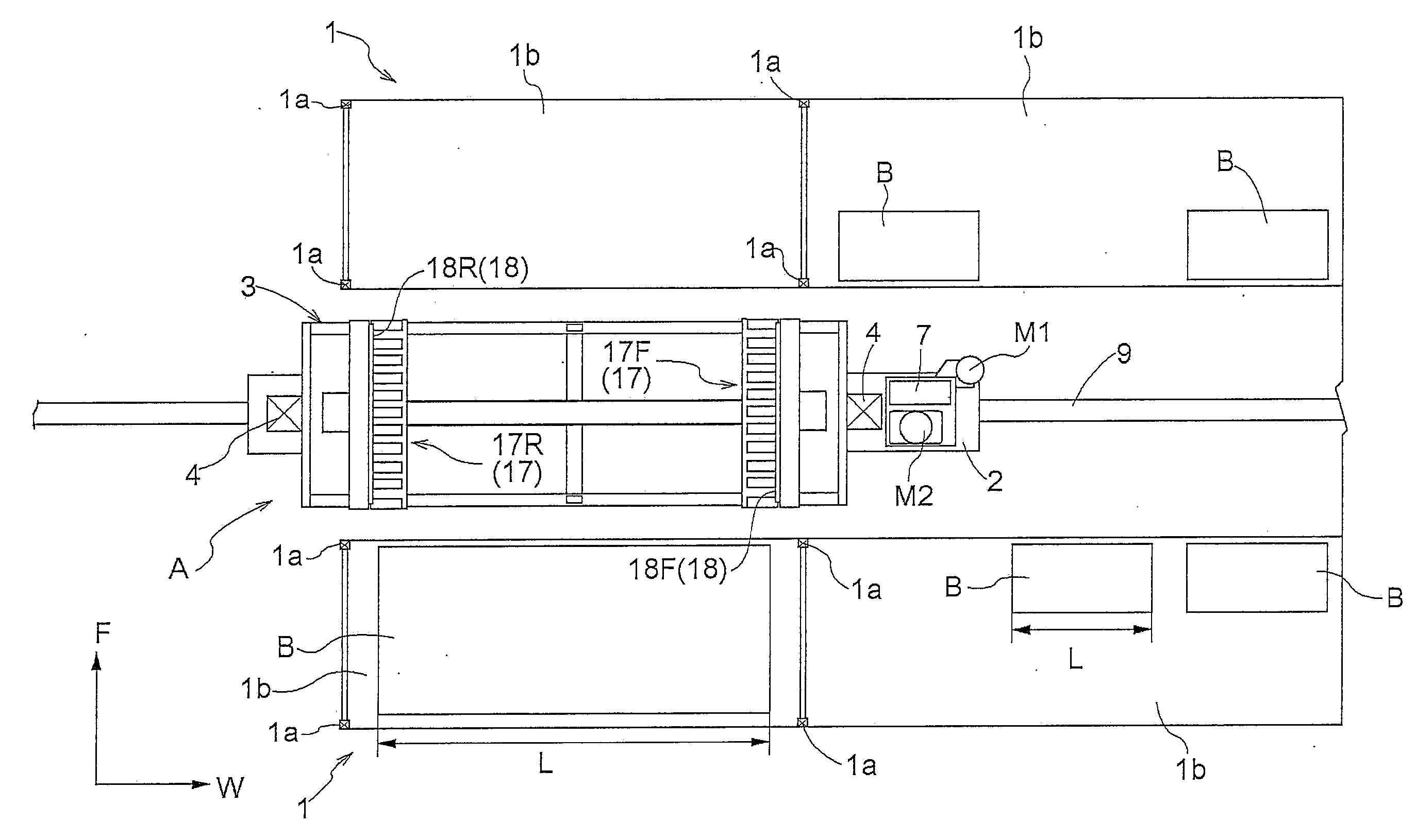
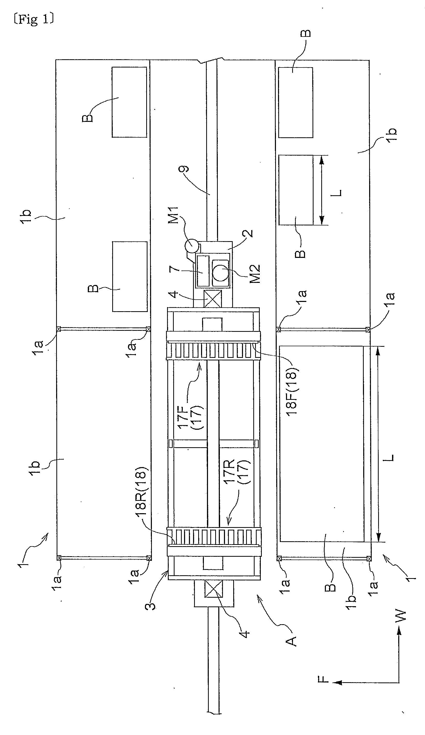
[0040]As shown in FIG. 1 and FIG. 2, the automated warehouse is provided with two storage racks 1 which are installed such that they are spaced apart from each other and such that their respective directions along which articles are moved in and out are opposite from each other, and a stacker crane A which runs along a work path formed between the storage racks 1.

[Storage Rack]

[0041]Each article storage rack 1 includes a plurality of support columns la that stand vertically and are spaced apart from each other in a rack lateral width direction (direction along W in FIG. 1) and in a rack fore and aft direction (direction along F in FIG. 1), and article support boards 1b that span between a plurality of the support columns la arranged in the rack lateral width ...


PUM


Abstract

An article transfer device includes a placement support portion that is provided to a base platform and includes a pair of divided placement support portions for separately receiving and supporting both side portions, in the article lateral direction, of the bottom surface of an article, and a pair of clamp portions that can be projected and retracted along an article transfer direction with respect to the placement support portion and can be moved toward and away from each other by a clamp actuator between gripping positions and releasing positions that are spaced apart wider. The pair of divided placement support portions can be moved toward and away from each other within a movable range defined in the article lateral direction by a placement support portion actuator and to face each other in close proximity when located in approach limit positions of the movable range.

Description

FIELD OF THE INVENTION [0001]The present invention relates to an article transfer device, and more specifically to an article transfer device for transferring two or more kinds of articles having different lengths in an article lateral direction which is perpendicular to an article transfer direction comprising a placement support portion that is provided to a base platform and that receives and supports an article to be transferred; a pair of clamp portions that are configured to be moved along the article transfer direction with respect to the placement support portion, and that are capable of being moved toward and away from each other between gripping positions for gripping the article to be transferred and releasing positions that are spaced apart wider than the gripping positions; and a clamp actuator for moving the pair of clamp portions toward and away from each other.BACKGROUND ART [0002]The article transfer device described above is provided in, for example, an article tra...

Claims


Application Information

Patent Timeline
Patent Type & Authority Applications(United States)
IPC IPC(8): B65G1/04
CPCB65G1/0435B65G1/0407B65G1/04B66F9/07
Inventor FUJITA, TAKASHI
Owner DAIFUKU CO LTD
Why Eureka
Try Eureka