

Zoom lens system and imaging device having the same
a zoom lens and imaging device technology, applied in the direction of instruments, optical elements, mountings, etc., can solve the problems of insufficient peripheral light security, difficult setting of the microlens pupil, and insufficient optical performance of image sensors
- Summary
- Abstract
- Description
- Claims
- Application Information
AI Technical Summary
Benefits of technology
Problems solved by technology
Method used
Image

Examples
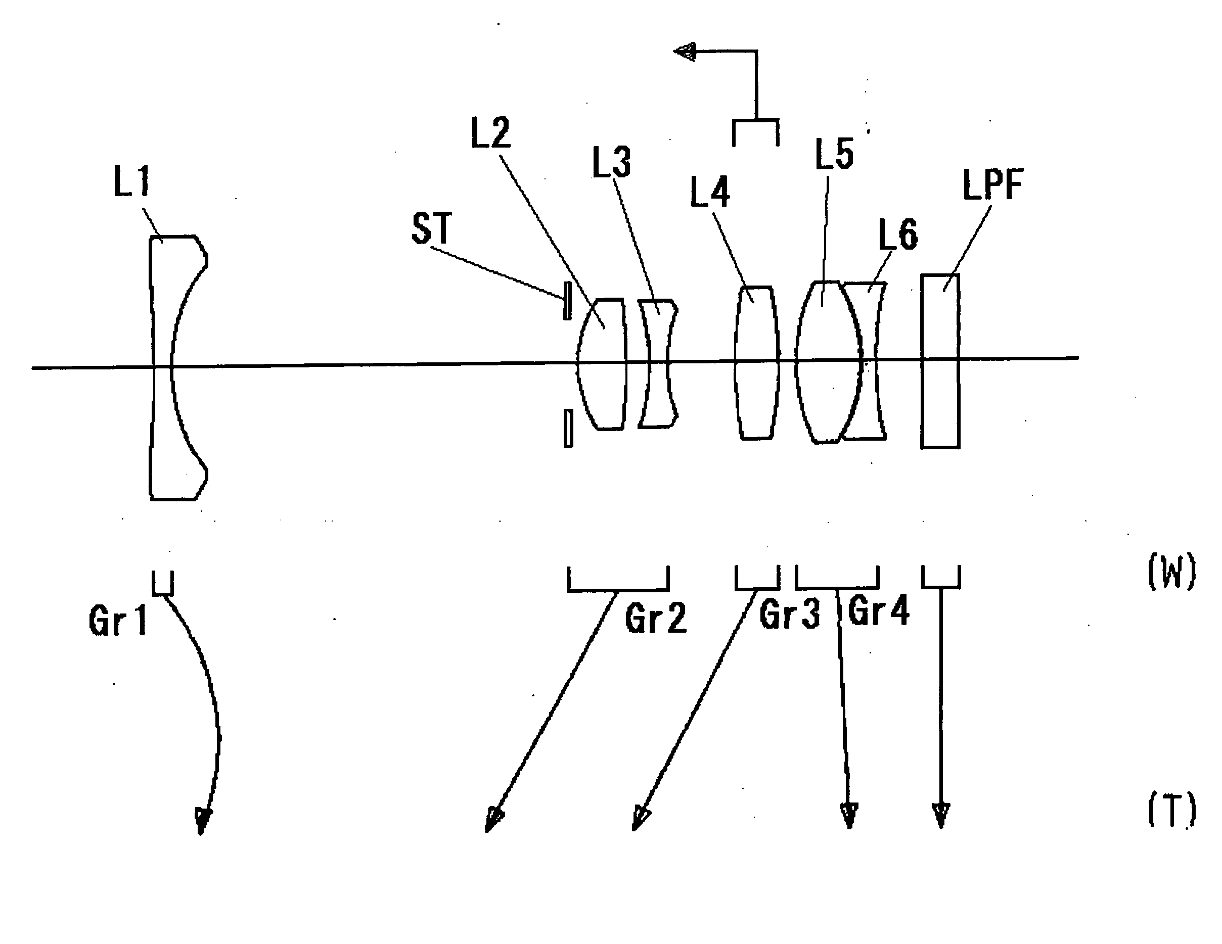
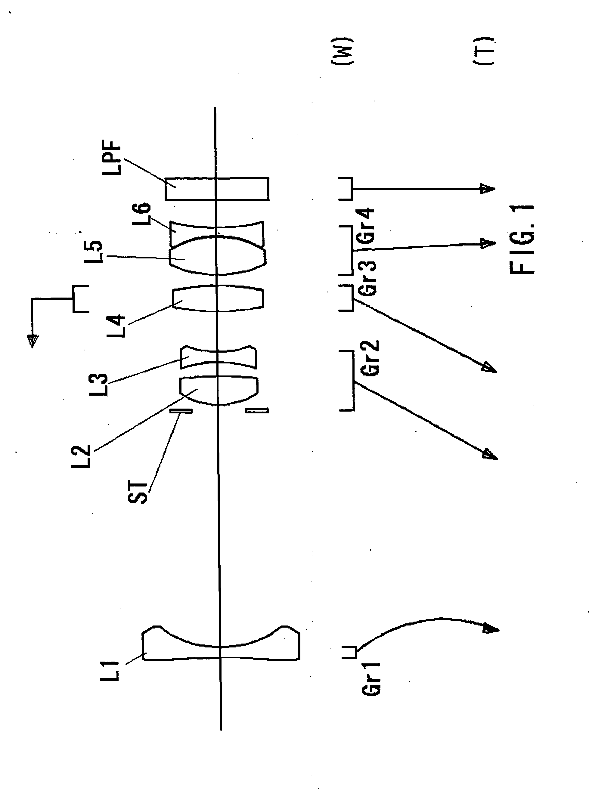
example 1
f = 6.0 − 10.8 − 17.3 mmFNo. = 2.95 − 3.46 − 4.24[Radius of Curvature][Axial Distance][Refractive Index(Nd)][Abbe Number(νd)]r1* = −180.565d1 = 1.000N1 = 1.49310ν1 = 83.58r2* = 8.101d2 = 22.102 −8.977 − 3.301r3 = ∞d3 = 0.600r4 = 6.286d4 = 2.725N2 = 1.74159ν2 = 43.17r5 = −29.861d5 = 1.300r6* = −11.145d6 = 1.000N3 = 1.84666ν3 = 23.82r7* = 10.004d7 = 3.742 −4.916 − 4.596r8 = 21.104d8 = 2.414N4 = 1.80513ν4 = 44.41r9 = −20.523d9 = 1.000 −6.985 − 16.317r10 = 10.089d10 = 3.566N5 = 1.48749ν5 = 70.44r11 = −8.086d11 = 0.100r12 = −7.873d12 = 0.800N6 = 1.58340ν6 = 30.23r13* = 25.439d13 = 2.550 −2.460 − 1.116r14 = ∞d14 = 2.000N7 = 1.51633ν7 = 64.14r15 = ∞[Aspherical Coefficient]r1ε = 0.10000E+01A4 = −0.75826E−03A6 = 0.34105E−04A8 = −0.50991E−06A10 = 0.25871E−08r2ε = 0.10000E+01A4 = −0.10941E−02A6 = 0.26338E−04A8 = 0.51284E−06A10 = −0.16952E−07r6ε = 0.10000E+01A4 = −0.31416E−03A6 = 0.93704E−05A8 = 0.43331E−05A10 = −0.34297E−06r7ε = 0.10000E+01A4 = 0.55006E−03A6 = 0.43702E−04A8 = 0.29782E−05A10 = ...
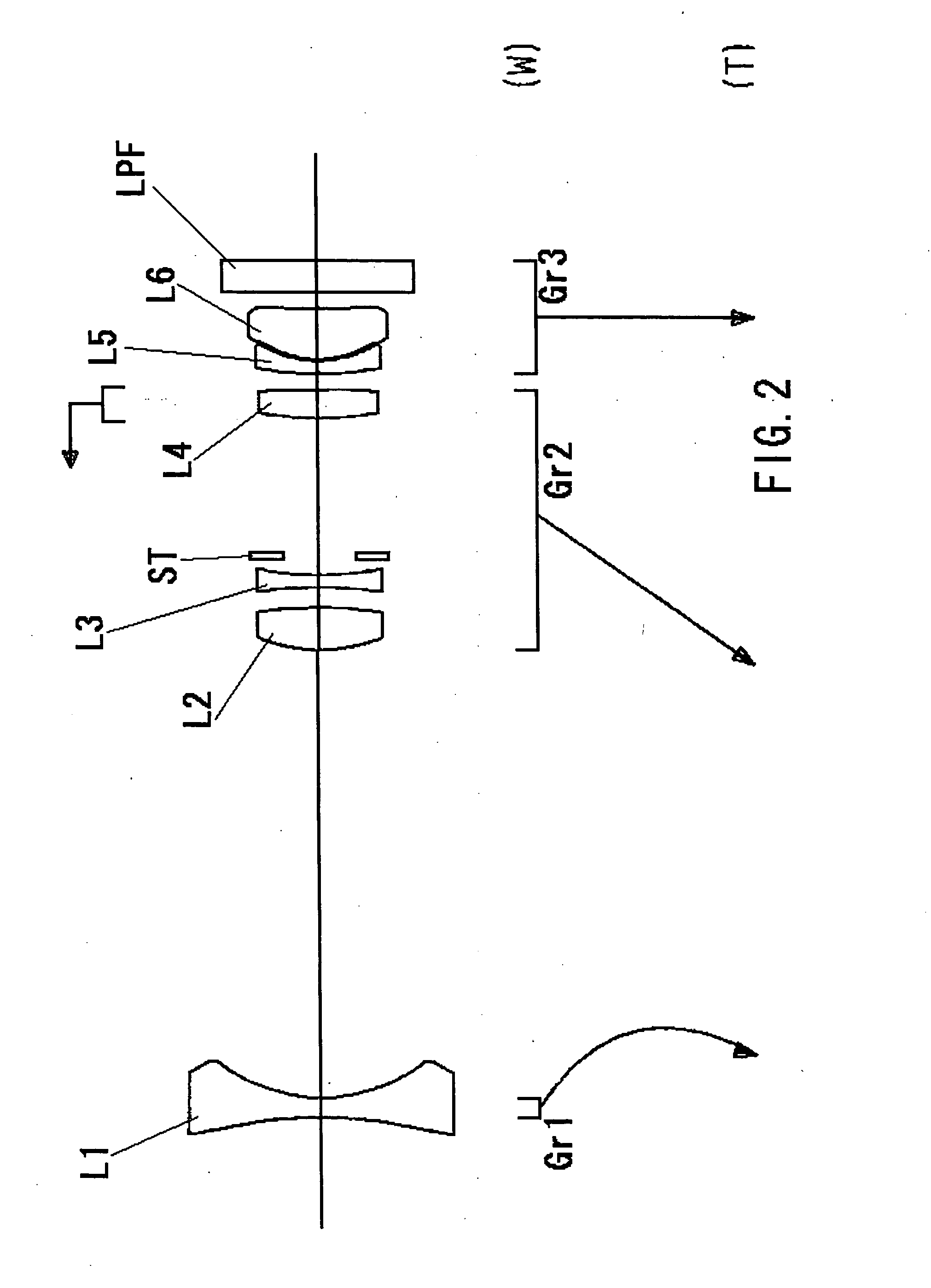
example 2
f = 5.6 − 16.1 − 21.2 mmFNo. = 2.95 − 4.51 − 5.27[Radius of Curvature][Axial Distance][Refractive Index(Nd)][Abbe Number(νd)]r1* = −39.852d1 = 1.200N1 = 1.49310ν1 = 83.58r2* = 7943d2 = 27.324 −5.086 − 2.210r3 = 9.089d3 = 2.617N2 = 1.75450ν2 = 51.57r4 = −26.827d4 = 1.220r5* = −45.076d5 = 0.800N3 = 1.84666ν3 = 23.82r6* = 18.718d6 = 1.188r7 = ∞d7 = 8.466r8 = 19.274d8 = 1.710N4 = 1.76213ν4 = 50.28r9 = −79.564d9 = 1.000 −13.487 − 19.631r10 = 19.602d10 = 0.800N5 = 1.79850ν5 = 22.60r11 = 6.499d11 = 0.100r12* = 5.624d12 = 3.076N6 = 1.52510ν6 = 56.38r13* = 67.250d13 = 1.000r14 = ∞d14 = 2.000N7 = 1.51680ν7 = 64.20r15 = ∞[Aspherical Coefficient]r1ε = 0.10000E+01A4 = −0.64385E−03A6 = 0.20445E−04A8 = −0.22702E−06A10 = 0.79381E−09r2ε = 0.10000E+01A4 = −0.10137E−02A6 = 0.90231E−05A8 = 0.49260E−06A10 = −0.10596E−07r5ε = 0.10000E+01A4 = −0.61443E−03A6 = 0.40451E−04A8 = −0.38476E−05A10 = 0.18991E−06r6ε = 0.10000E+01A4 = −0.28745E−03A6 = 0.58066E−04A8 = −0.54298E−05A10 = 0.27306E−06r12ε = 0.10000E+01A...
example 3
f = 5.6 − 16.1 − 21.3 mmFNo. = 2.95 − 4.07 − 4.61[Radius of Curvature][Axial Distance][Refractive Index(Nd)][Abbe Number(νd)]r1* = −35.240d1 = 1.200N1 = 1.49310ν1 = 83.58r2* = 8.469d2 = 27.719 −4.808 − 1.846r3 = 8.794d3 = 2.582N2 = 1.74754ν2 = 51.81r4 = −25.730d4 = 0.600r5 = ∞d5 = 0.600r6* = −42.662d6 = 0.800N3 = 1.84666ν3 = 23.82r7* = 17.339d7 = 8.811r8 = 18.677d8 = 2.126N4 = 1.78578ν4 = 46.80r9 = −72.376d9 = 1.000 −12.250 − 17.785r10 = 21.040d10 = 0.800N5 = 1.79850ν5 = 22.60r11 = 6.402d11 = 0.115r12* = 5.787d12 = 3.146N6 = 1.52510ν6 = 56.38r13* = 69.497d13 = 1.000r14 = ∞d14 = 2.000N7 = 1.51680ν7 = 64.20r15 = ∞[Aspherical Coefficient]r1ε = 0.10000E+01A4 = −0.62293E−03A6 = 0.22312E−04A8 = −0.26635E−06A10 = 0.96658E−09r2ε = 0.10000E+01A4 = −0.92271E−03A6 = 0.10117E−04A8 = 0.59055E−06A10 = −0.13036E−07r6ε = 0.10000E+01A4 = −0.68242E−03A6 = 0.42598E−04A8 = −0.36680E−05A10 = 0.18704E−06r7ε = 0.10000E+01A4 = −0.32785E−03A6 = 0.63607E−04A8 = −0.55179E−05A10 = 0.28183E−06r12ε = 0.10000E+01...
PUM
| Property | Measurement | Unit |
|---|---|---|
| optical power | aaaaa | aaaaa |
| focal length | aaaaa | aaaaa |
| Abbe number | aaaaa | aaaaa |
Abstract
Description
Claims
Application Information