
Interlocking component assembly for an expandable rack assembly

a technology of interlocking components and rack assemblies, which is applied in the direction of feet, dismountable cabinets, cabinets, etc., can solve the problems of disproportionate storage and delivery costs to production costs, lack of rigidity, and bulky assembly of furnitur

Inactive Publication Date: 2010-08-03
CHOI YING KIT
View PDF47 Cites 19 Cited by
  • Summary
  • Abstract
  • Description
  • Claims
  • Application Information

AI Technical Summary

Benefits of technology

"The present invention provides an interlocking component assembly for an expandable rack assembly that is easy to assemble and adjustable to meet users' needs. The assembly includes horizontally and vertically-deposed panels, middle joint components, and interlocking components. The middle joint components are positioned between the horizontally-deposed panels and the vertically-deposed panels, and the interlocking components connect the panels together. The assembly also includes a plurality of assist vertically-deposed panels that allow the middle joint components to penetrate therethrough. The technical effects of the invention include easy assembly and adjustability of the interlocking component assembly, as well as improved stability and flexibility of the expandable rack assembly."

Problems solved by technology

Assembled furniture is bulky, and incurs storage and delivery costs disproportionate to its production costs; packaged RTA furniture occupies little more volume than that of its components, and can be shipped at far lower cost.
However, conventional fasteners often lack sufficient rigidity to effectively support and hold the assembled rack structure in secured position, which in turn makes the rack assembly structure unable to sustain and hold objects with heavy weight.
Further, the panels or frame unit that constitute a rack assembly are manufactured by standardization according to specifications, thus lacking flexibility in applications if the user desires to add more frame units for expanding the assembled rack structure.
As such, the conventional rack assembly structures are known to have disadvantages of insufficient structural rigidity and inconvenient application.
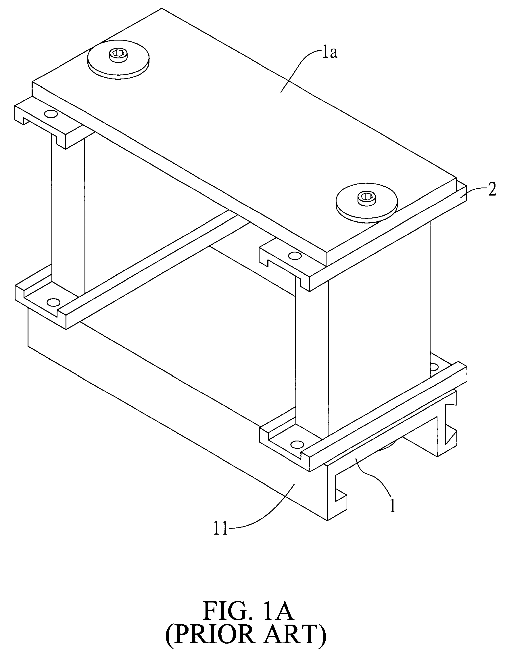
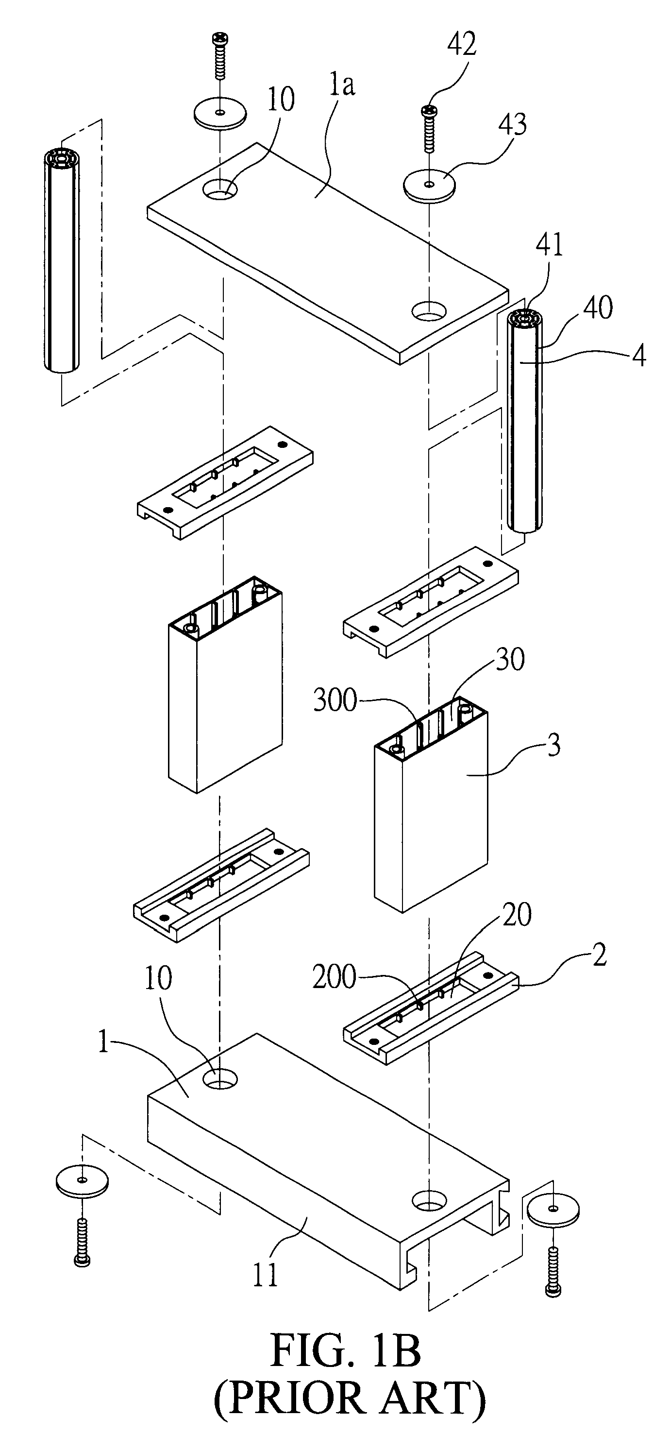
Because the frame unit is often posited at a corner location where assembly is to be completed, it is cumbersome and inconvenient to have an extended interlocking member 4 easily assembled under the awkward situation.

Method used


Image

  • Interlocking component assembly for an expandable rack assembly
  • Interlocking component assembly for an expandable rack assembly
  • Interlocking component assembly for an expandable rack assembly

Examples


first preferred embodiment

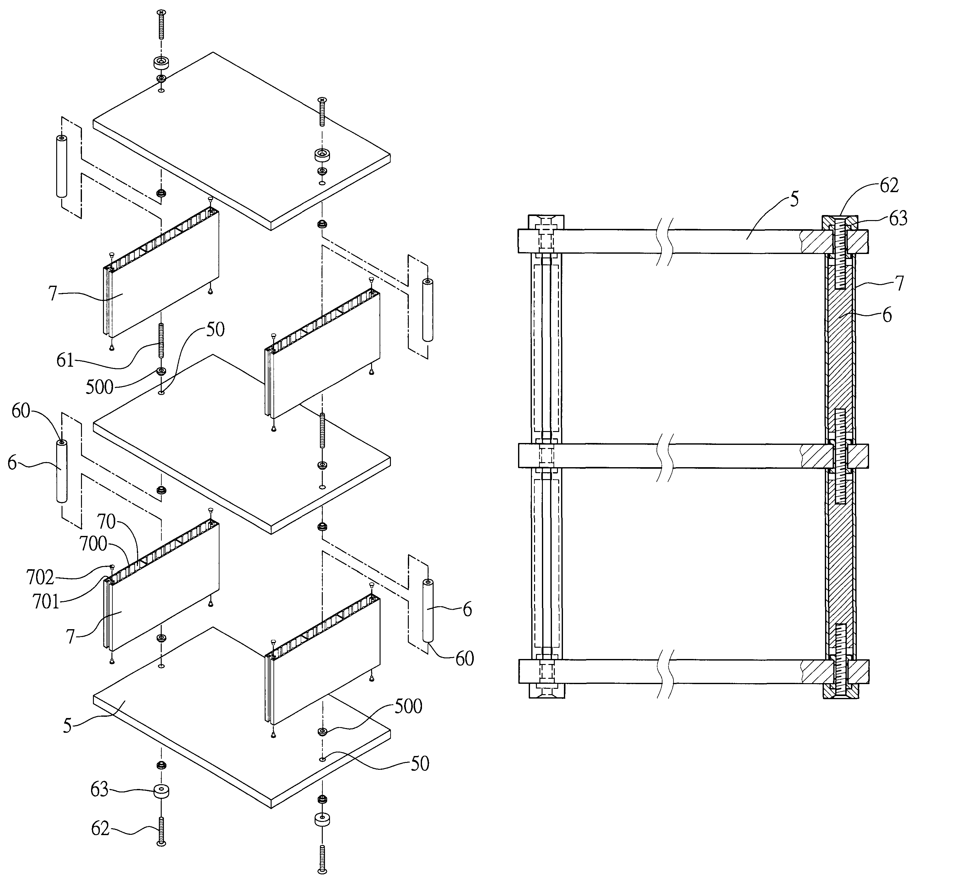
[0031]FIGS. 2A to 2C illustrate the first embodiment of an interlocking component assembly of an expandable rack assembly in accordance with the present invention. As shown, the interlocking component assembly of an expandable rack assembly of the present invention includes a plurality of horizontally-deposed panels 5; a plurality of vertically-deposed panel 7 each disposed between two horizontally-deposed panels 5; a plurality of middle joint components 6 each disposed in the vertically-deposed panel 7; and a plurality of interlocking components 61 each disposed to penetrate through and interconnect the horizontally-deposed panel 5 with the vertically-deposed panel 7.

[0032]Each of horizontally-deposed panel 5 is formed with a first opening 50 and may include a protective sheath 500 covered thereon for protecting the peripheral surface corresponding to the first opening 50, wherein the horizontally-deposed panel 5 may be made of one selected from the group of materials consisting of...

second preferred embodiment

[0040]FIGS. 3A to 3B depict the second embodiment of the interlocking component assembly of an expandable rack assembly according to the present invention. In this illustrated embodiment, an alternative design of the vertically-deposed panel 7 and middle joint components 6 as is shown in FIGS. 2A and 2C respectively.

[0041]As shown in FIGS. 3A and 3B, the middle joint component 6a is a cylindrical body having a plurality of spaced out second positioning portions 64, which may be but are not limited to a groove, disposed on the peripheral wall thereof. Each vertically-deposed panel 7a is formed with a second opening 70a in which a plurality of spaced out first positioning portions 700a, which may be but is not limited to a protruding rib, are disposed on each of two opposed inner walls of the second opening 70a to form a plurality of interconnected rectangular apertures, wherein each of first positioning portions 700a is adapted to correspondingly couple with each of the second positi...

third preferred embodiment

[0042]FIGS. 4A and 4B depict the third embodiment of the interlocking component assembly of an expandable rack assembly according to the present invention. In this illustrated embodiment, another alternative design of the vertically-deposed panel 7 and middle joint components 6 as is shown in FIGS. 2A and 2C respectively.

[0043]As shown in FIGS. 4A and 4B, the middle joint component 6b is a rectangular pillar in which a plurality of spaced out second positioning portions 64b, which may be but is not limited to a groove, are disposed on each of two opposed end portions thereof.

[0044]Each of the vertically-deposed panel 7b is formed with a second opening 70b in which a plurality of spaced out first positioning portions 700b, which may be but is not limited to a protruding rib, are on each of two opposed inner walls of the second opening 70b to form a plurality of interconnected rectangular apertures, wherein each of first positioning portions 700b is adapted to correspondingly couple w...


PUM

PropertyMeasurementUnit
lengthaaaaaaaaaa
heightaaaaaaaaaa
outer diameteraaaaaaaaaa

Abstract

An interlocking component assembly of an expandable rack assembly is proposed, including a plurality of horizontally-deposed panels each formed with a first opening, a plurality of vertically-deposed panels each disposed between two horizontally-deposed panels, a plurality of middle joint components each disposed in vertically-deposed panels, and a plurality of interlocking components each adapted for interconnecting two middle joint components to interconnect and fasten the horizontally-deposed panel to the vertically-deposed panel, wherein the height of the vertically-deposed panel is greater than the length of the middle joint component, such that the vertically-deposed panel can be coupled to the interlocking component to securely engage the horizontally-deposed panel with the vertically-deposed panel, thereby enabling the rack assembly to be free from limitations of assembling locations or dimensional specifications while the structural rigidity and strength of the assembled rack unit is enhanced.

Description

BACKGROUND OF THE INVENTION[0001]1. Field of the Invention[0002]The present invention generally relates to interlocking component assemblies and, more particular, to an interlocking component assembly of an expandable rack assembly to hold a variety of objects for display or storage purposes, in a manner to preserve the integrity of each object.[0003]2. Description of Prior Art[0004]Do it yourself, often referred to by the acronym DIY, that focus on people creating things for themselves without the aid of paid professionals, is a common trend in modern societies. As such, Ready-to-assemble furniture, also known as “knock-down furniture” or “flat packs”, is furniture supplied as a kit of flat parts and fasteners to be assembled, usually by the end user, with simple tools, become very common and popular. Assembled furniture is bulky, and incurs storage and delivery costs disproportionate to its production costs; packaged RTA furniture occupies little more volume than that of its compo...

Claims


Application Information

Patent Timeline
Patent Type & Authority Patents(United States)
IPC IPC(8): A47B47/00
CPCA47B47/04A47B2087/023A47B47/0075
Inventor CHOI, YING-KIT
Owner CHOI YING KIT
Learn More