Variable power optical system and image pickup apparatus having the same

a pickup apparatus and optical system technology, applied in the field of variable power optical system and image pickup apparatus, can solve the problems of chromatic aberration of magnification at the telephoto end position, strong refractive power of a second lens group,

Inactive Publication Date: 2012-07-12
OM DIGITAL SOLUTIONS CORP
View PDF2 Cites 19 Cited by
  • Summary
  • Abstract
  • Description
  • Claims
  • Application Information

AI Technical Summary

Benefits of technology

[0035]The present invention can offer a variable power optical system in which aberrations are corrected well while the value of the total length of the variable power optical system relative to image height is being made to become small, and an image pickup apparatus having the same.

Problems solved by technology

When an attempt to achieve a super-small-sized variable power optical system is made, the refractive power of a second lens group becomes strong, so that chromatic aberration of magnification at the telephoto end position becomes a problem.

Method used


Image

  • Variable power optical system and image pickup apparatus having the same
  • Variable power optical system and image pickup apparatus having the same
  • Variable power optical system and image pickup apparatus having the same

Examples


embodiment 1

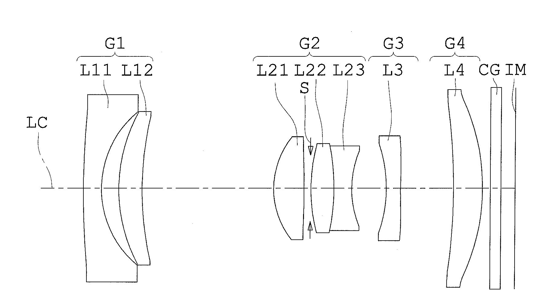
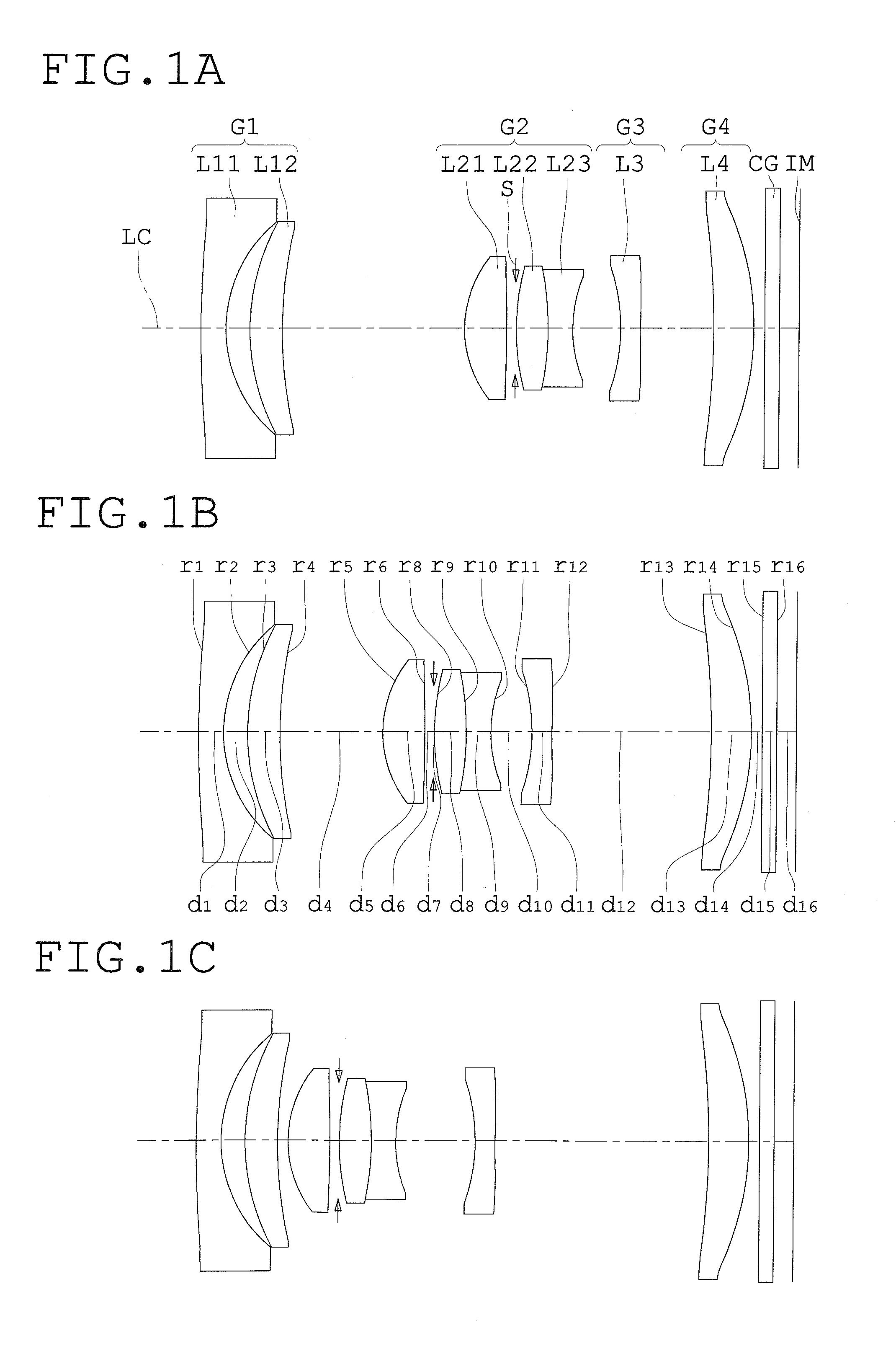
[0235]The optical constitution of the variable power optical system of the present embodiment is explained using FIG. 1. The total length of the variable power optical system of the present embodiment is about 13 mm. The variable power optical system of the present embodiment includes, in order from the object side, a first lens group G1 with negative refractive power, a second lens group G2 with positive refractive power, a third lens group G3 with negative refractive power, and a fourth lens group G4 with positive refractive power, these lens groups being located on the optical axis Lc.

[0236]The first lens group G1 is composed of a negative meniscus lens L11 the convex surface of which faces toward the object side and a positive meniscus lens L12 the convex surface of which faces toward the object side, in that order from the object side. And, the first lens group G1 as a whole has negative refractive power.

[0237]The second lens group G2 includes a first lens element with positive...

embodiment 2

[0241]The optical constitution of the variable power optical system of the present embodiment is explained using FIG. 5. The total length of the variable power optical system of the present embodiment is about 13 mm.

[0242]The variable power optical system of the present embodiment includes, in order from the object side, a first lens group G1 with negative refractive power, a second lens group G2 with positive refractive power, a third lens group G3 with negative refractive power, and a fourth lens group G4 with positive refractive power, these lens group being located on the optical axis Lc.

[0243]The first lens group G1 is composed of a negative meniscus lens L11 the convex surface of which faces toward the object side and a positive meniscus lens L12 the convex surface of which faces toward the object side, in that order from the object side. And, the first lens group G1 as a whole has negative refractive power.

[0244]The second lens group G2 includes a first lens element with posi...

embodiment 3

[0249]The optical constitution of the variable power optical system of the present embodiment is explained using FIG. 9. The total length of the variable power optical system of the present embodiment is about 16 mm.

[0250]The variable power optical system of the present embodiment includes, in order from the object side, a first lens group G1 with negative refractive power, a second lens group G2 with positive refractive power, a third lens group G3 with positive refractive power, and a fourth lens group G4 with positive refractive power, these lens groups being located on the optical axis Lc.

[0251]The first lens group G1 is composed of one biconcave negative lens L1.

[0252]The second lens group G2 is composed of one positive meniscus lens L2 the convex surface of which faces toward the object side.

[0253]The third lens group G3 includes a first lens element with positive refractive power, a second lens element, and a third lens element, in that order from the object side. The second ...


PUM


Abstract

A variable power optical system includes, in order from the object side, a first lens group having negative refractive power, a variable power group having positive refractive power, and a final lens group having positive refractive power. The variable power group is provided with, in order from the object side, a first lens element having positive refractive power, a second lens element, and a third lens element. The second lens element has a convex shape on the object side. The final lens group includes a positive lens. The variable power optical system satisfies the following conditions:
10≦VdLg≦45
−1.0<(R2a−R2b)/(R2a+R2b)<1.0
where VdLg is the Abbe number of the positive lens of the final lens group with respect to the d line, R2a is the curvature radius of the object-side surface of the second lens element, and R2b is the curvature radius of the image-side surface of the third lens element.

Description

[0001]This application claims benefits of Japanese Application No. 2009-212134 filed in Japan on Sep. 14, 2009, No. 2009-212135 filed in Japan on Sep. 14, 2009 and No. 2009-212136 filed in Japan on Sep. 14, 2009, the contents of which are hereby incorporated by reference.BACKGROUND OF THE INVENTION[0002]1. Field of Invention[0003]This invention relates to a variable power optical system in which aberrations are corrected well while the value of the total length of the optical system relative to image height is being made to become small, and to an image pickup apparatus having the same.[0004]2. Description of the Related Art[0005]Digital cameras, which are provided with a solid-state imaging sensor like CCD (Charge Coupled Device) or CMOS (Complementary Metal-Oxide Semiconductor), have become mainstream instead of film-based cameras in recent years. These digital cameras include various kinds of digital cameras which range from high performance-type digital camera for business to co...

Claims


Application Information

Patent Timeline
Patent Type & Authority Applications(United States)
IPC IPC(8): H04N5/232G02B13/04
CPCG02B15/177G02B13/009G02B15/144511
Inventor MATSUO, KEIGOMIMURA, TAKAYUKIADACHI, KANATOGOTO, HISASHI
Owner OM DIGITAL SOLUTIONS CORP
Why Eureka
Try Eureka