Coaxial connector

Inactive Publication Date: 2005-02-03
HIROSE ELECTRIC GROUP
View PDF6 Cites 21 Cited by
  • Summary
  • Abstract
  • Description
  • Claims
  • Application Information

AI Technical Summary

Benefits of technology

[0015] Further, it is preferred that the reinforcing portion has a corner cut in a tapered shape and adjacent to the bent connecting portion connected to the cylindrical portion. If the corner has the right angle or round shape, the tool for pulling out the connector abuts against only the corner and is inclined, so that the tool does not contact a lower edge of the reinforcing portion over the whole length thereof. As a result, the tool is easy to come off. The lid is connected to the cylindrical portion through the connecting portion within a limited area. The corner is located near the connecting portion, and a point of application is far from the connecting portion, i.e. a base point receiving the bending force. Accordingly, the projecting portions receive a large bending moment, thereby applying the pulling force on a weak site of the projecting portions.
[0016] The lid portion firmly holds the cable with the holding portion thereof at a side where the cable extends. Therefore, when the corner is cut in a tapered shape, the tool abuts against the projecting portions at a side where the cable extends, so that the holding portion as well supports the pulling force. In this case, the point of application is near the base point, thereby reducing bending momen

Problems solved by technology

In this case, the one contacting portion located at a position where the cable extends tends to deform in the

Method used


Image

  • Coaxial connector
  • Coaxial connector
  • Coaxial connector

Examples


Embodiment Construction

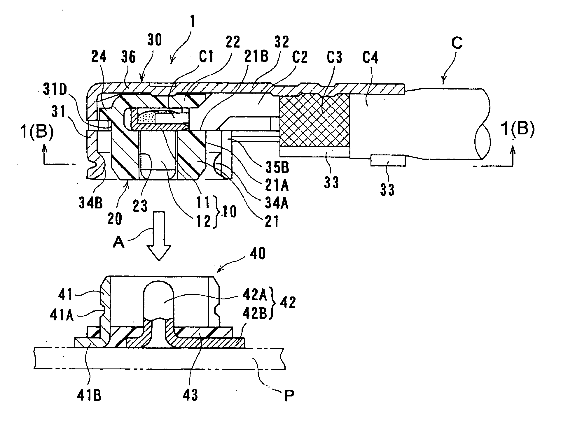
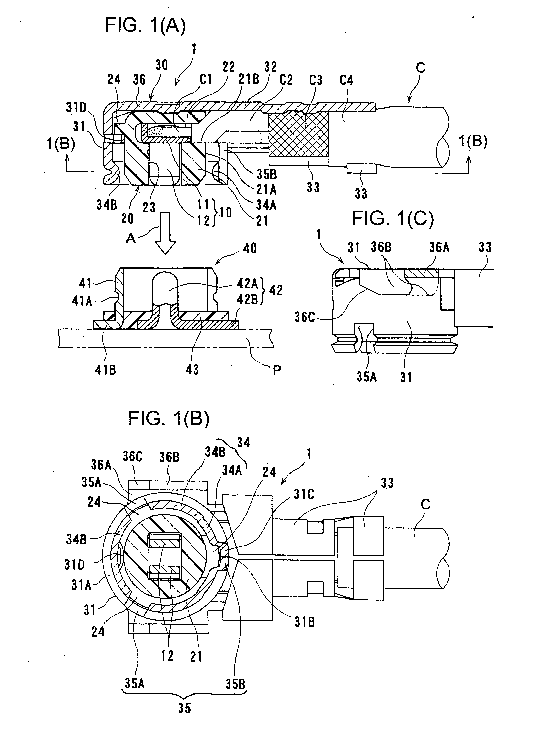
[0024] Hereunder, embodiments of the present invention will be explained with reference to the accompanying drawings. FIGS. 1(A) to 1(C) are views showing a right angle coaxial connector according to an embodiment of the invention, wherein FIG. 1(A) is a sectional view of the right angle connector before being connected to a corresponding connector, FIG. 1(B) is a sectional view thereof taken along a line 1(B)-1(B) in FIG. 1(A), and FIG. 1(C) is a partial sectional view thereof.

[0025] A coaxial connector 1 has a central conductor 10 and an outer conductor 30 integrated together via a dielectric member 20. A coaxial cable C is connected to the connector 1. The central conductor 10 is formed of a molded metal plate. As shown in FIG. 1(A), the central conductor 10 has a connecting portion 11 having an L shape section and a pair of contacting portions 12 having an elastic tongue shape and extending downwardly from the connecting portion 11 in parallel to each other. A core wire C1 of t...


PUM


Abstract

A right angle coaxial connector is fitted into a corresponding connector in a fitting direction substantially perpendicular to a direction that a connecting cable extends. The right angle coaxial connector includes an outer conductor having a cylindrical portion with an axial line in the fitting direction and a lid portion covering an inner space of the cylindrical portion and extending over a covering portion of the connecting cable. The lid portion is integrated with the cylindrical portion at a part of a periphery of the cylindrical portion through a bent connecting portion. The lid portion includes a holding portion at an extending end thereof for pressingly holding the connecting cable. The cylindrical portion includes engaging portions for engaging the corresponding connector. One of the engaging portions located at a position where the cable extends has an engaging amount larger than that of the other engaging portions at other positions.

Description

BACKGROUND OF THE INVENTION AND RELATED ART STATEMENT [0001] The present invention relates to a coaxial connector, especially, a right angle coaxial connector. [0002] A coaxial connector called a right angle coaxial connector is fitted into a corresponding connector in a direction perpendicular to a direction that a coaxial cable extends, and has been widely used for connecting a circuit board. [0003] As disclosed in Japanese Patent Publication No. 2001-43939, a conventional right angle coaxial connector includes an outer conductor having a cylindrical portion to be connected to an external terminal of a corresponding connector, and a lid portion integrated with the cylindrical portion for covering an upper portion of the cylindrical portion. In forming the outer conductor, a metal plate is first press-molded to form the cylindrical portion, and then the metal plate is bent to form the lid portion. The cylindrical portion is connected to the lid portion at a part of a periphery ther...

Claims


Application Information

Patent Timeline
IPC IPC(8): H01R13/639H01R13/627
CPCH01R9/0518H01R2103/00H01R13/6277
Inventor IKEDA, KAZUHIKOASANO, NAOYUKI
Owner HIROSE ELECTRIC GROUP
Why Eureka
Try Eureka