Inflatable sling and method for positioning a patient

a patient and inflatable technology, applied in the field of air mattresses, can solve the problem that the attendant may not have enough strength to help the patient move, and achieve the effect of distributing the weigh

Active Publication Date: 2012-08-23
D T DAVIS ENTERPRISES LTD D B A HOVERTECH INT
View PDF8 Cites 19 Cited by
  • Summary
  • Abstract
  • Description
  • Claims
  • Application Information

AI Technical Summary

Benefits of technology

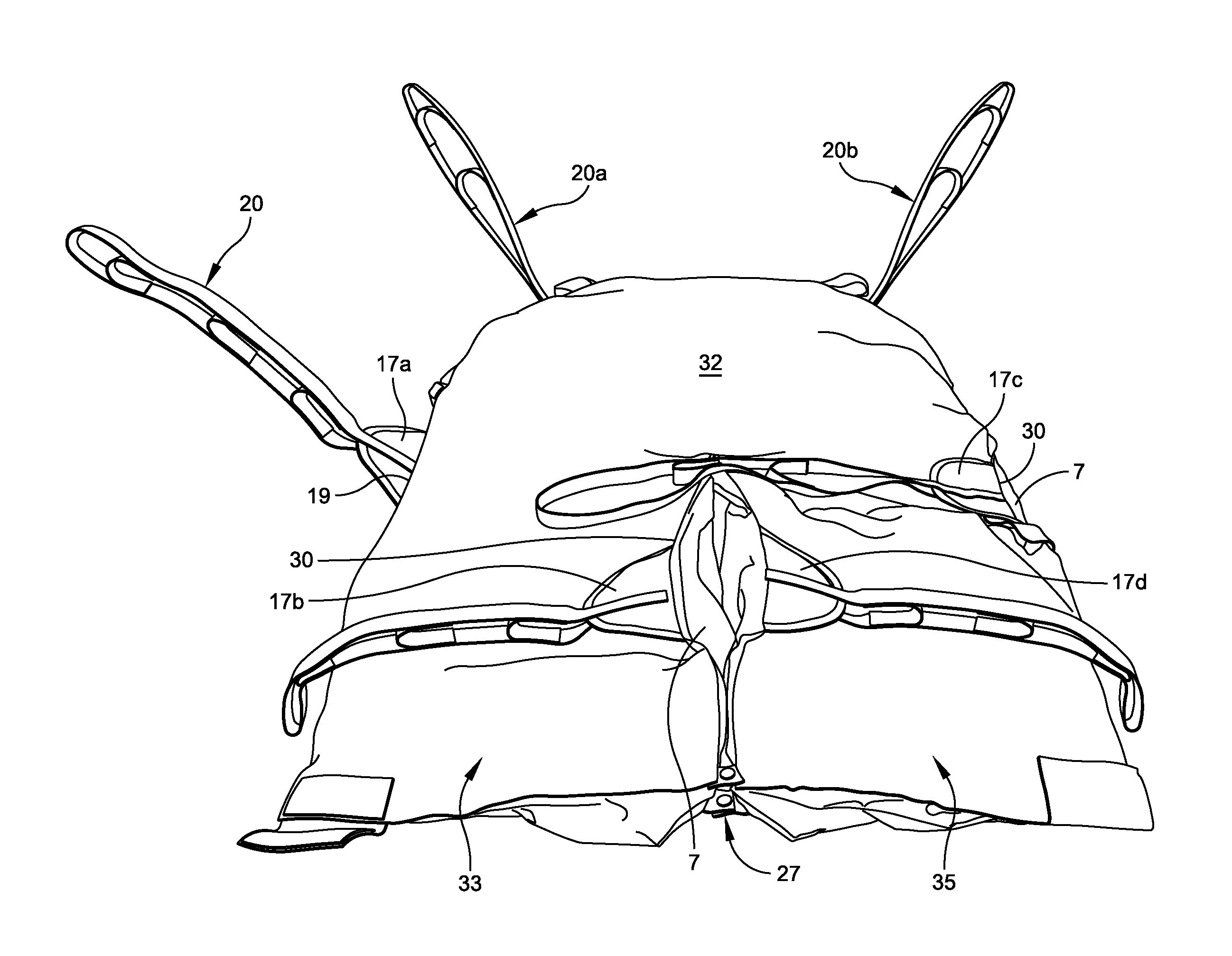
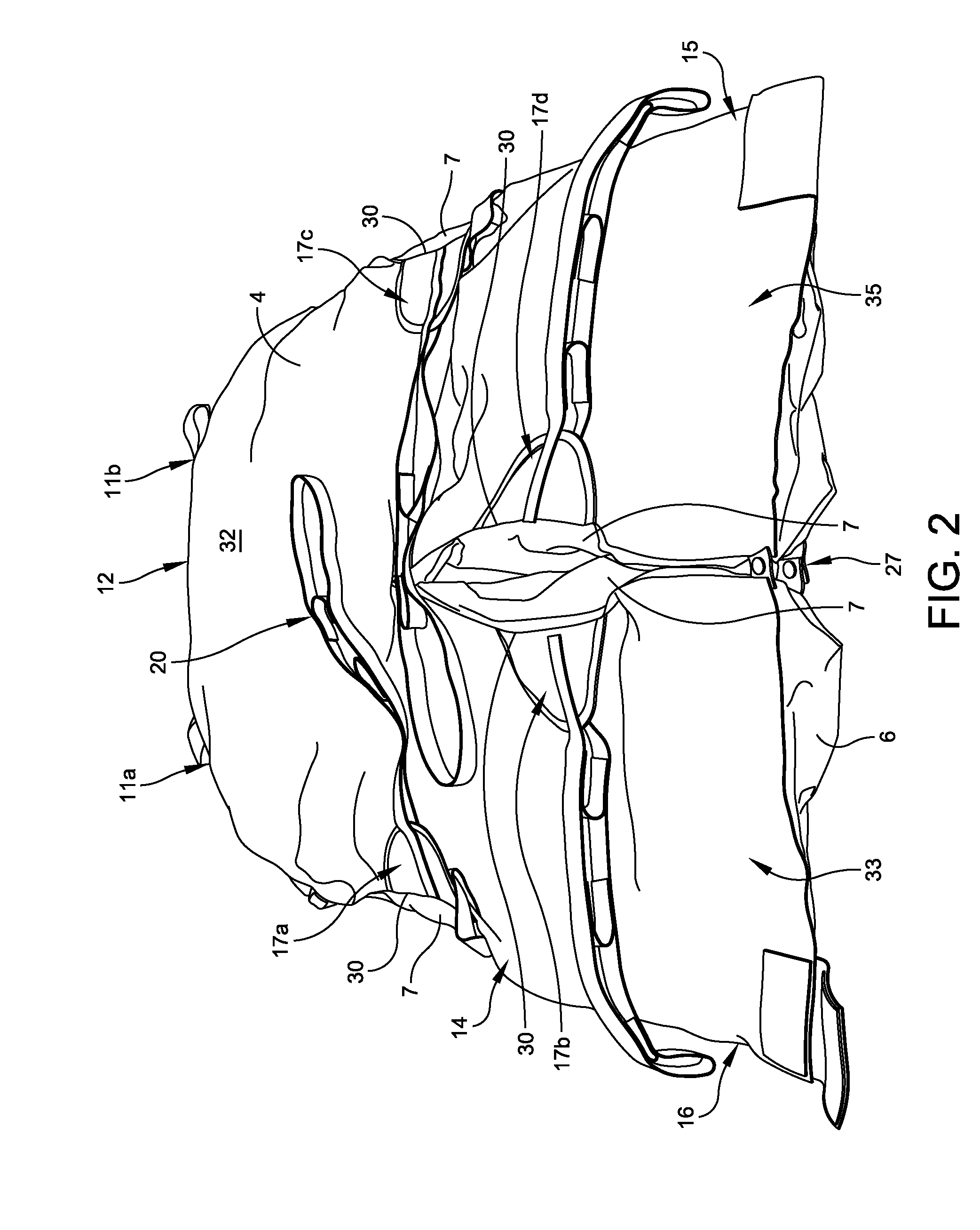
[0008]In another embodiment, a patient transfer device is provided with a torso support pad, a first leg and a second leg. The first leg extends out from a portion of the torso support pad and includes a first strap anchor fastened to an outer seam and releasably interconnected to an outer strap. A second strap anchor is fastened to an inner seam of the first leg and releasably interconnected to an inner strap. Advantageously, the first and second strap anchors are longitudinally off-set from one another so as to provide an equal distribution of weight across the leg when a patient is positioned upon the transfer device. The second leg is spaced from the first leg and extends out from a portion of the torso support pad. The second leg includes a third strap anchor fastened to an outer seam and releasably interconnected to an outer strap and a fourth strap anchor fastened to an inner seam and releasably interconnected to an inner strap. Here again, the third and fourth strap anchors are longitudinally off-set from one another so as to provide an equal distribution of weight across the leg when a patient is positioned upon the transfer device.

Problems solved by technology

In many cases, such patients often are also too heavy to lift or, the attendant may not have enough strength to help the patient move.

Method used


Image

  • Inflatable sling and method for positioning a patient
  • Inflatable sling and method for positioning a patient
  • Inflatable sling and method for positioning a patient

Examples


Embodiment Construction

[0026]This description of preferred embodiments is intended to be read in connection with the accompanying drawings, which are to be considered part of the entire written description of this invention. The drawing figures are not necessarily to scale and certain features of the invention may be shown exaggerated in scale or in somewhat schematic form in the interest of clarity and conciseness. In the description, relative terms such as “horizontal,”“vertical,”“up,”“down,”“top” and “bottom” as well as derivatives thereof (e.g., “horizontally,”“downwardly,”“upwardly,” etc.) should be construed to refer to the orientation as then described or as shown in the drawing figure under discussion. These relative terms are for convenience of description and normally are not intended to require a particular orientation. Terms including “inwardly” versus “outwardly,”“longitudinal” versus “lateral” and the like are to be interpreted relative to one another or relative to an axis of elongation, or...


PUM


Abstract

An inflatable mattress-sling having an inflatable torso support pad, a first leg extending out from a first portion of the inflatable torso support pad, and a second leg spaced from the first leg and extending out from a second portion of the inflatable torso support pad. The legs include straps attached to their inner and outer seams so as to facilitate lifting of a patient.

Description

CROSS-REFERENCE TO RELATED APPLICATIONS[0001]This application claims priority under 35 U.S.C. §119(e) from copending Provisional Application Ser. No. 61 / 443,901, filed Feb. 17, 2011.FIELD OF THE INVENTION[0002]The present invention generally relates to devices for lifting or transferring patients, and more particularly to air mattresses that allow for both sliding transfers of a patient and lifting of the patient.BACKGROUND OF THE INVENTION[0003]Personal lift or patient lift devices have been known and used in the past for the purpose of assisting with the mobility of otherwise immobilized patients. An attendant may help physically disabled patients who may suffer from a traumatic injury, a stroke, obesity, or another form of illness that renders them unable to move about. In many cases, such patients often are also too heavy to lift or, the attendant may not have enough strength to help the patient move.[0004]Personal lift devices that have been used in the past typically include a...

Claims


Application Information

Patent Timeline
Patent Type & Authority Applications(United States)
IPC IPC(8): A61G7/14
CPCA61G7/1028A61G7/1051A61G7/1025A61G2200/32A61G2200/34A61G7/1059A61G7/10A61G1/044A47C27/08
Inventor DAVIS, DAVID T.
Owner D T DAVIS ENTERPRISES LTD D B A HOVERTECH INT
Why Eureka
Try Eureka