Split power tool

a power tool and split technology, applied in the field of split power tools, can solve the problems that current available power tools may not have the desired adaptability or versatility

Active Publication Date: 2012-08-23
MTD PRODUCTS
View PDF5 Cites 21 Cited by
  • Summary
  • Abstract
  • Description
  • Claims
  • Application Information

AI Technical Summary

Problems solved by technology

However, currently available power tools may not have the desired adaptability or versatility for

Method used


Image

  • Split power tool
  • Split power tool
  • Split power tool

Examples


Embodiment Construction

[0025]Reference will now be made in detail to the presently preferred embodiments of the invention, examples of which are illustrated in the accompanying drawings.

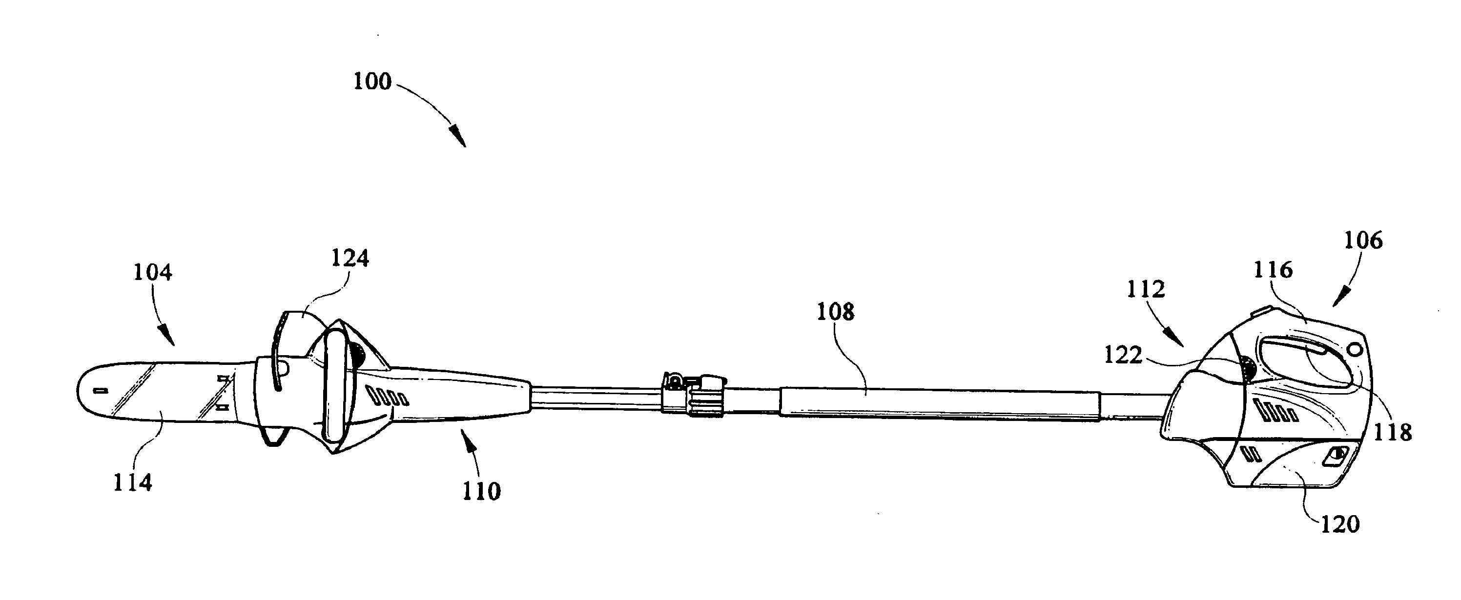
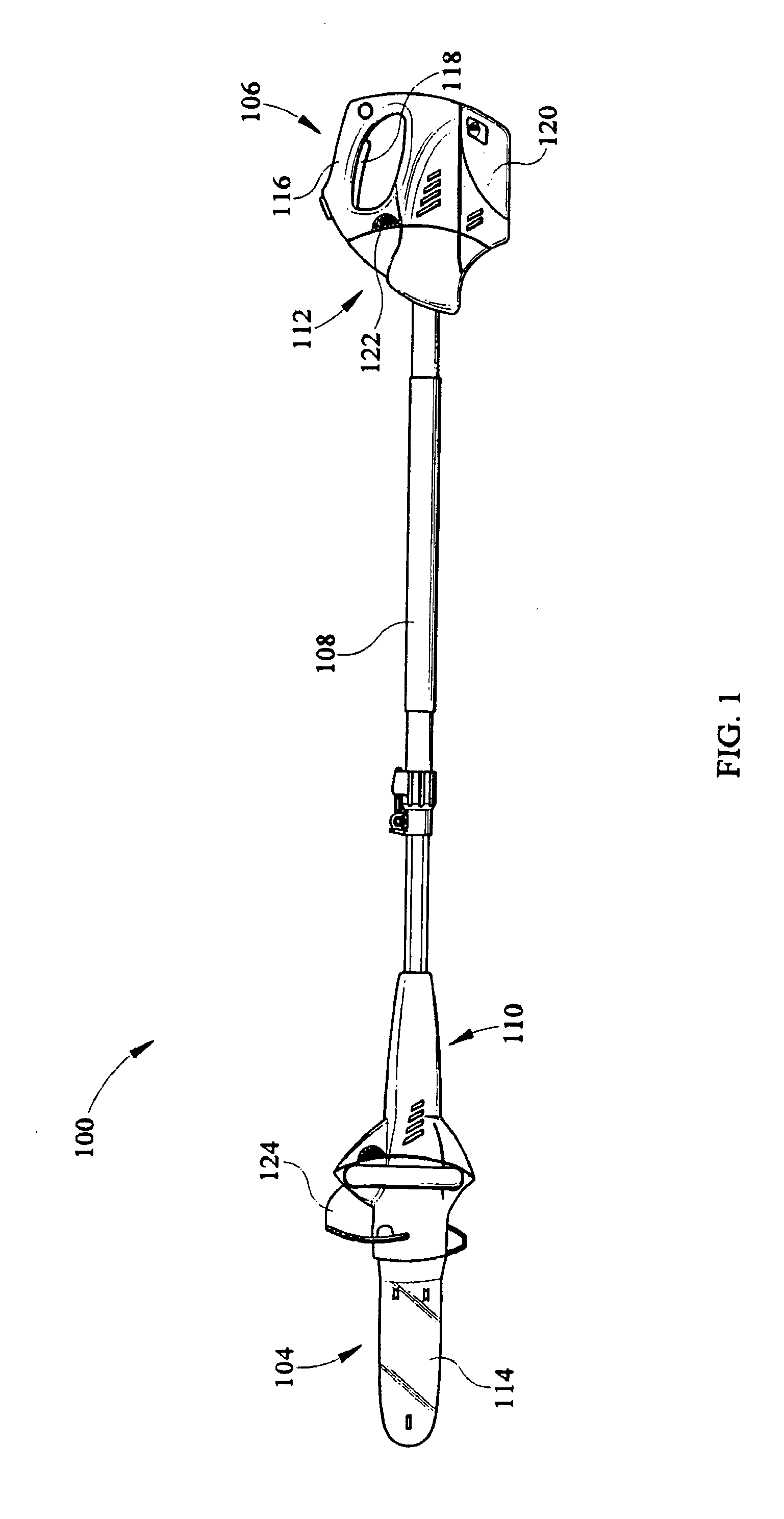
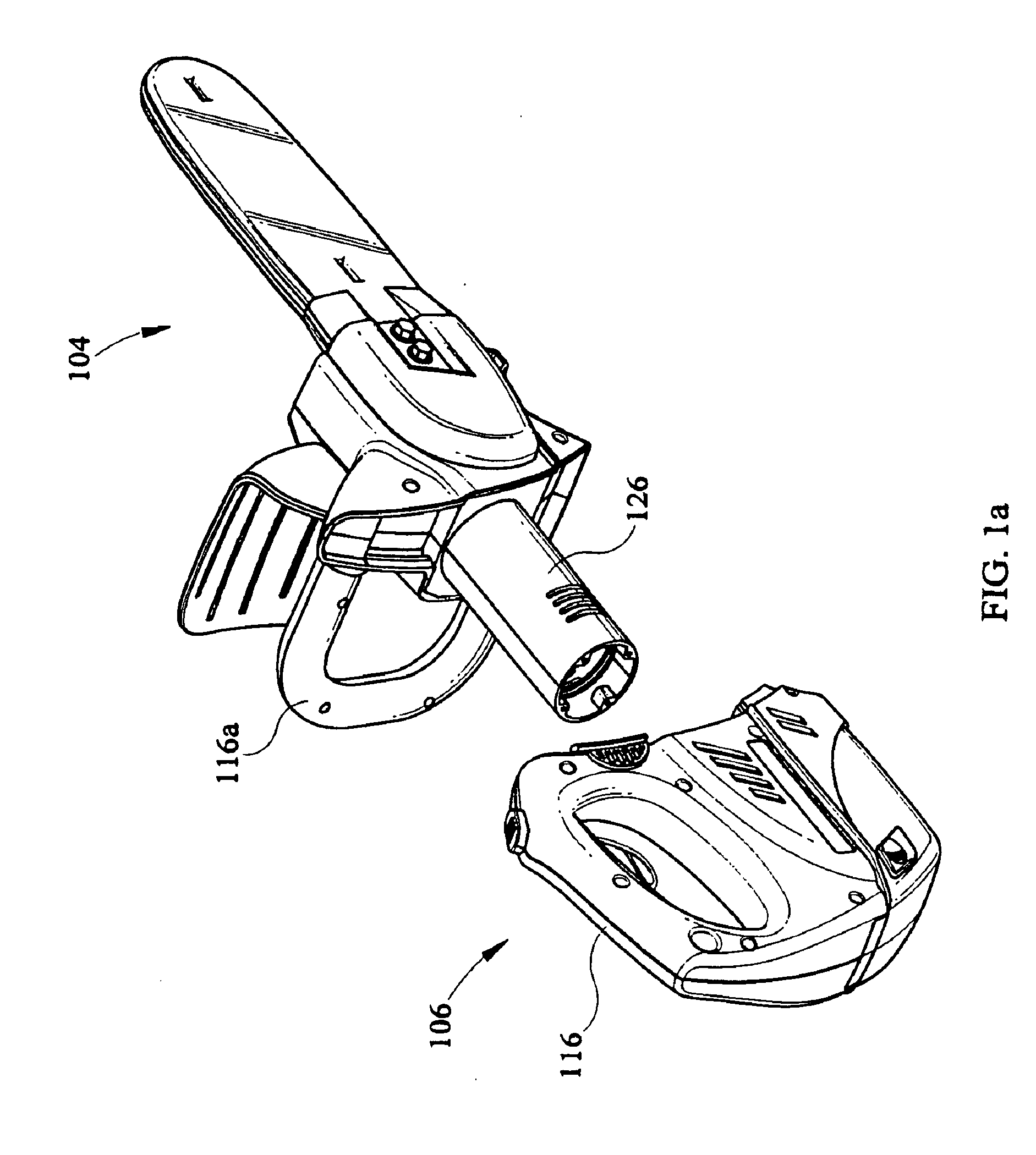
[0026]Turning now to the Figures and specifically to FIG. 1, an expandable power tool 100 includes a housing 102 having a tool or power head end 104 and a handle end 106 separated by a power tool extension device or pole 108. In one embodiment, the pole 108 is a telescoping pole whose length is adjustable. The pole 108 shown in FIGS. 1 and 7-12 has a first end 110 that mechanically and electrically attaches to the power head end 104 of the power tool and a second end 112 that attaches to the handle or actuation end 106 of the tool. In the exemplary embodiment shown in FIG. 1, the tool or power head end 104 has a saw 114 attached, but other types of tools such as hedge trimmers (FIG. 12), various power heads or other gardening implements can be used. The handle end 106 has a guard 116a as well as a handle 116 with a trigger...


PUM


Abstract

An extendable hedge trimmer includes a housing having a handle end and a tool end. The handle end includes a battery and an electrical connector. The tool end includes a hedge trimming implement, a motor, and an electrical connector. The electrical connector of the tool end is electrically connected with the motor. Wiring is included within the handle end for electrically connecting the battery and the electrical connector of the handle end. The trimmer also includes a pole which is releasably connectable between the tool end and the handle end. The pole is configured for electrically connecting the handle end with the tool end. The trimmer also includes a latch mechanism for releasably attaching the pole between tool end and handle end. The trimmer also includes an input for receiving AC line power via a power cord, the trimmer configured for being power by AC line power and/or battery power.

Description

CROSS REFERENCE TO RELATED APPLICATIONS[0001]The present application is a continuation-in-part application and claims priority under 35 U.S.C. §120 to U.S. patent application Ser. No. 12 / 012,788 filed Feb. 5, 2008, which is a continuation-in-part application claiming priority to U.S. patent application Ser. No. 11 / 756,214 filed May 31, 2007, which is a non-provisional application claiming priority to U.S. Provisional Application Ser. No. 60 / 888,535 filed Feb. 6, 2007.FIELD OF INVENTION[0002]The present invention generally relates to an extendable and reconfigurable power tool, and more particularly to a power tool having two halves and an extension pole that can be inserted between the two halves to electrically connect them and make the power head end of the tool operable even though separated from the actuation end.BACKGROUND OF THE INVENTION[0003]Power tools are implemented for a variety of tasks, such as for pruning a hedge, cutting low-hanging branches of trees, or the like. Ho...

Claims


Application Information

Patent Timeline
IPC IPC(8): B26B27/00A47L5/12
CPCA01G3/086A01G20/47B25F3/00B25F5/02B27B17/0008B27B17/0083Y10S30/01A01G3/053A01G3/08A01G3/085A47L9/2842B25G1/04B25G3/12B25G3/18
Inventor GIESKE, JASONBOCHMANN, CHERRY A.RIDDELL, ERIN Q.
Owner MTD PRODUCTS
Why Eureka
Try Eureka