Method and apparatus for rf-based ranging with multiple antennas

Inactive Publication Date: 2012-08-23
QUALCOMM INC
View PDF6 Cites 16 Cited by
  • Summary
  • Abstract
  • Description
  • Claims
  • Application Information

AI Technical Summary

Benefits of technology

[0014]In yet another aspect, a display is provided that includes a screen; a first antenna mounted at a first location on the screen; a second antenna mounted at a second location on the screen; and a controller coupled to the first and second antennas. The controller is configured to determine a first ranging measurement between the first antenna and a device antenna on a device; determine a second ranging measurement between the second antenna and the device antenna; and determine at least one of an orientation or the position of the apparatus relative to the device using the first and second ranging measurements to facilitate motion capture.
[0015]In yet another aspect, a remote control is provided that includes a housing; a first antenna mounted at a first location in the housing; a second antenna mounted at a second location in the housing; and a controller coupled to the first and second antennas. The controller is configured to determine a first ranging measurement between the first antenna and a device antenna on a device; determine a second ranging measurement between the second antenna and the device antenna; and determine at least one of an orientation or the position of the apparatus relative to the device using the first and second ranging measurements to facilitate motion capture

Problems solved by technology

Currently there are approaches based on inertial sensors only, but they do not know the exact orientation to the screen without user input such as orienting the device in a known orientation such as straight at the screen and pushing a button.
Similarly there are approaches based on infrared (IR), but they suffer from the IR receivers needing to be in the line of sight of the IR emitter.
For example, inertial sensors suffer from drift errors and visual feature recognition fails in situations that lack line of sight and suffer longer processing times. Other motion capture modalities, such as optical markers, require extensive and often expensive setup that is undesirable because it is cost prohibitive to purchase the equipment and because they prefer everything to operate with minimum setup.
However, cost of implementation increases with addition of RF nodes.

Method used


Image

  • Method and apparatus for rf-based ranging with multiple antennas
  • Method and apparatus for rf-based ranging with multiple antennas
  • Method and apparatus for rf-based ranging with multiple antennas

Examples


Embodiment Construction

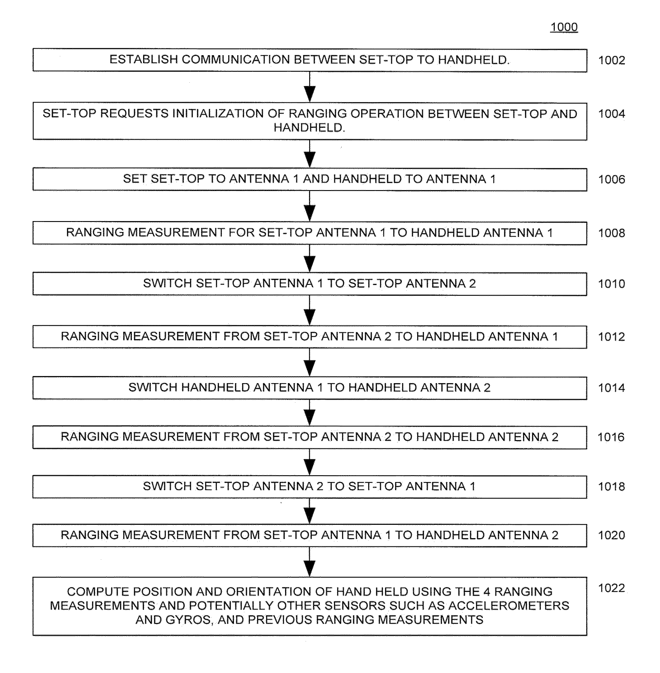
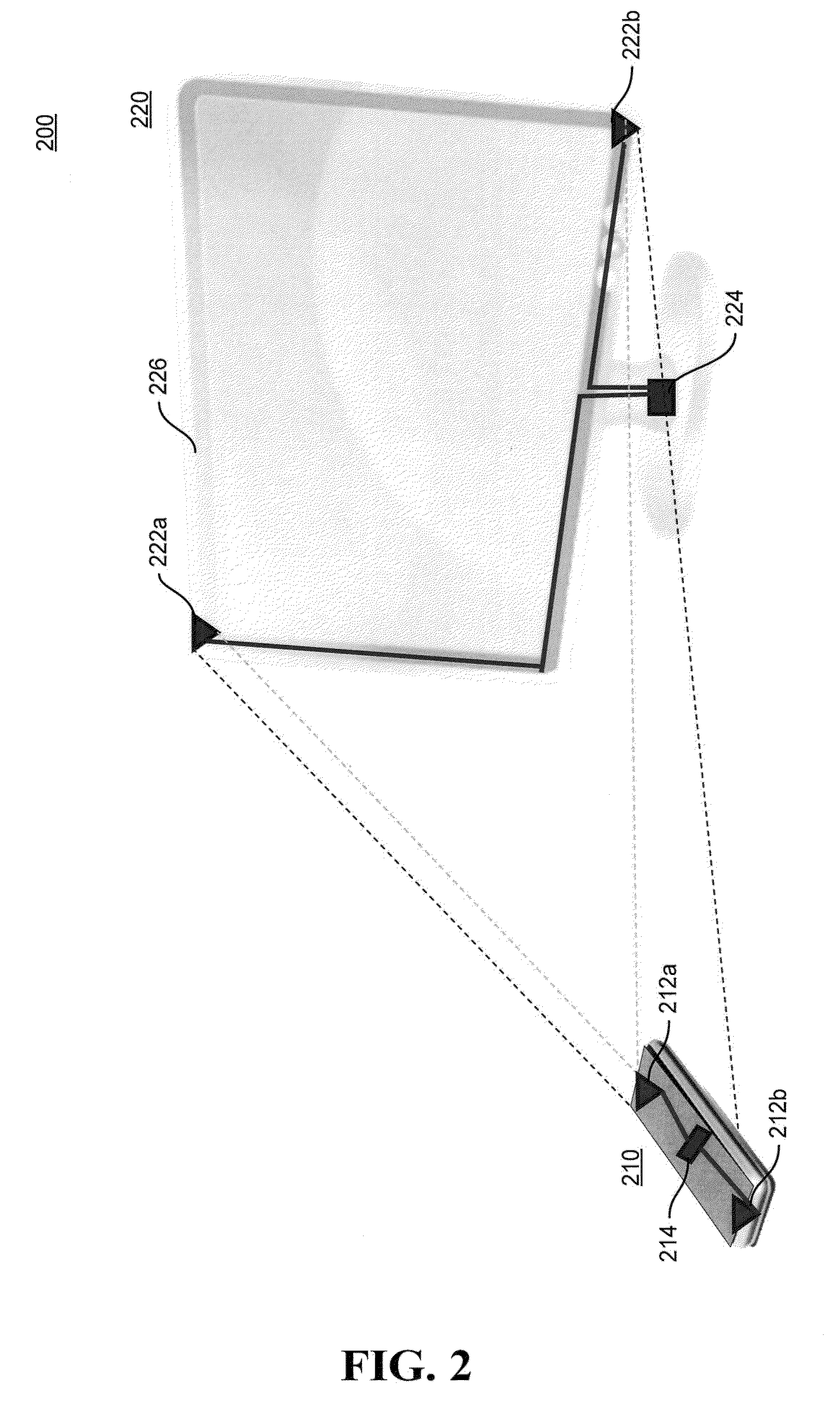
[0030]Various aspects of the disclosure are described more fully hereinafter with reference to the accompanying drawings. This disclosure may, however, be embodied in many different forms and should not be construed as limited to any specific structure or function presented throughout this disclosure. Rather, these aspects are provided so that this disclosure will be thorough and complete, and will fully convey the scope of the disclosure to those skilled in the art. Based on the teachings herein one skilled in the art should appreciate that the scope of the disclosure is intended to cover any aspect of the disclosure disclosed herein, whether implemented independently of or combined with any other aspect of the disclosure. For example, an apparatus may be implemented or a method may be practiced using any number of the aspects set forth herein. In addition, the scope of the disclosure is intended to cover such an apparatus or method which is practiced using other structure, functio...


PUM


Abstract

An apparatus having a first antenna; a second antenna; and a controller coupled to the first and second antennas, wherein the controller is configured to determine a first ranging measurement between the first antenna and a device antenna on a device; determine a second ranging measurement between the second antenna and the device antenna; and determine an orientation and position of the apparatus relative to the device by combining the first and second ranging measurements. A method for implementing the orientation and position process is also disclosed herein.

Description

CROSS-REFERENCE TO RELATED APPLICATION(S)[0001]This application claims priority to and benefit of U.S. Provisional Application Ser. No. 61 / 374,570 (Attorney Docket Number 102665P1), entitled “METHOD AND APPARATUS FOR RF-BASED RANGING WITH MULTIPLE ANTENNAS ON A NETWORK NODE,” filed on Aug. 17, 2010, which is expressly incorporated by reference herein in its entirety.BACKGROUND[0002]1. Field[0003]The present disclosure relates generally to determining a position and orientation of an apparatus with respect to another device, and more particularly, to an apparatus and methods for radio frequency (RF)-based ranging with multiple antennas.[0004]2. Background[0005]When using interactive media it is important to correctly identify a user's intent expressed, for example, by the user pointing a remote control or a body gesture. In a use example, with Internet browsing on TV, users have to interact with the display at the high accuracy that a PC desk mouse would deliver by pointing a remote ...

Claims


Application Information

Patent Timeline
IPC IPC(8): G01S3/02
CPCG01S5/021G01S5/0247G06F3/0346G01S5/14G01S5/0257G01S5/02585
Inventor KIRBY, MILES ALEXANDER LYELLJULIAN, DAVID JONATHANBURDO, RINAT
Owner QUALCOMM INC
Why Eureka
Try Eureka