
Glass cleaning device

Active Publication Date: 2008-02-14
PROBASCO TIMOTHY PAUL
View PDF11 Cites 18 Cited by
  • Summary
  • Abstract
  • Description
  • Claims
  • Application Information

AI Technical Summary

Benefits of technology

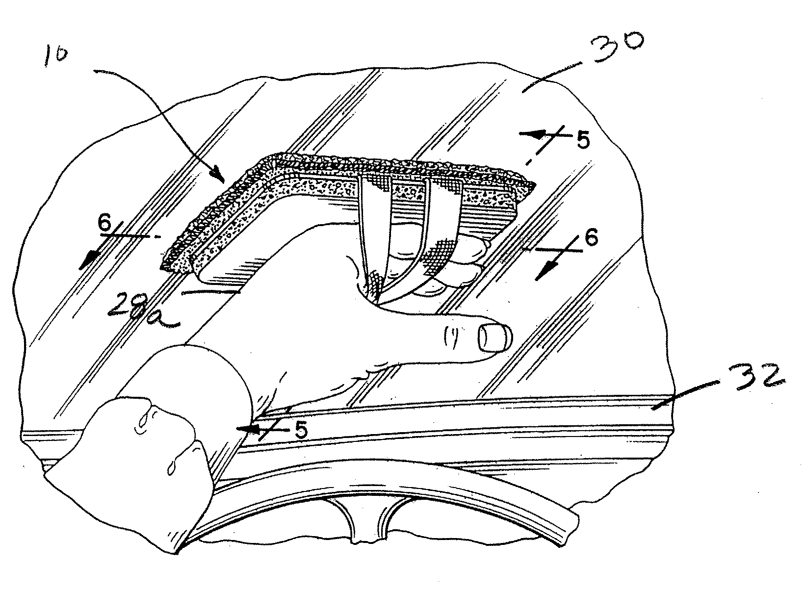
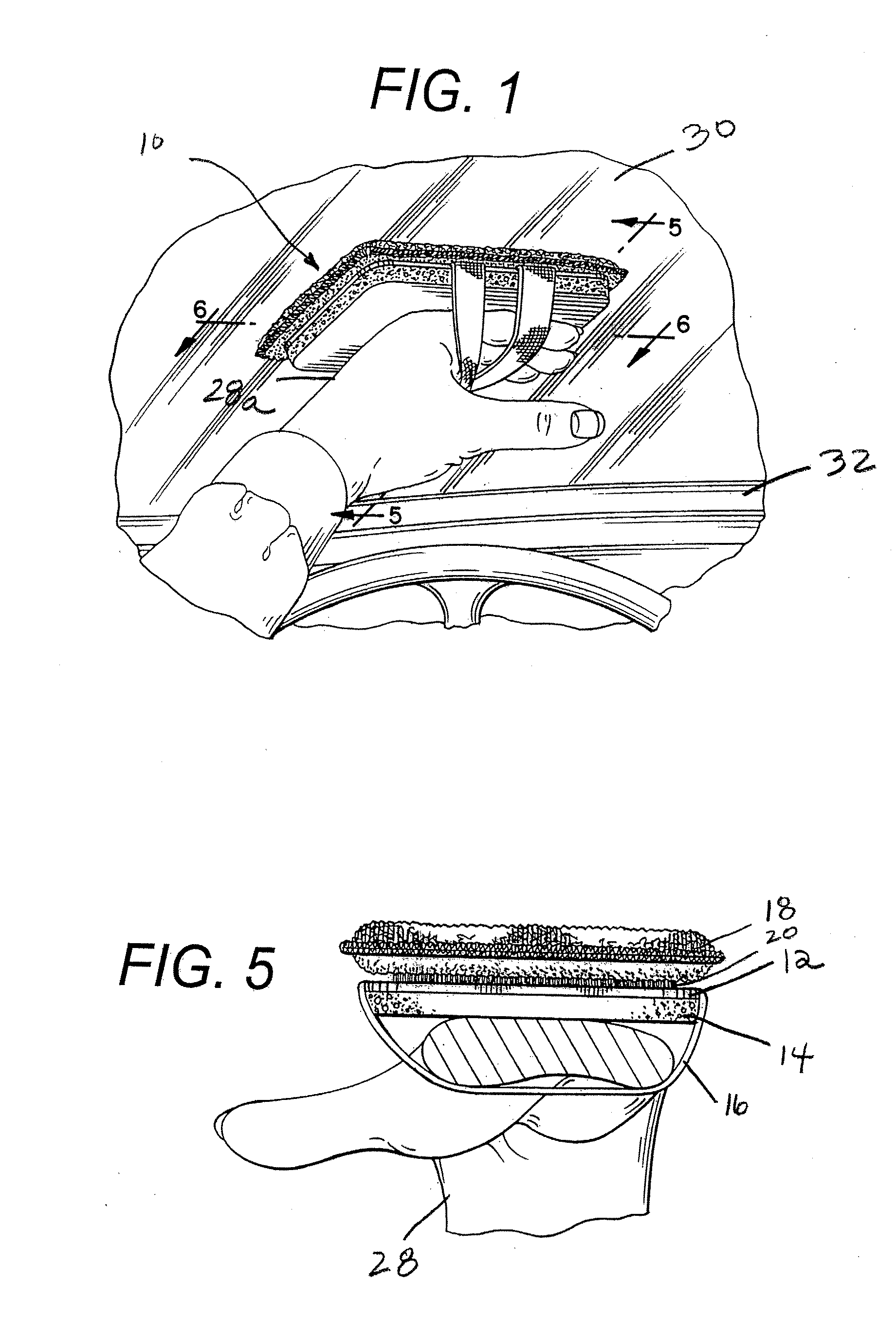
[0005]The present invention relates to a cleaning device such as for the inside surface of a vehicle windshield. The cleaning device can be used to clean angled surfaces in vehicles, such as windshields and dashboards, or any other angular surface. The device can also be utilized to clean other glass and non-angular surfaces. The cleaning device is designed to attach to the user's hand in a manner which permits the cleaning device to be positioned on the backside of the user's hand, i.e., the side of the hand opposite the user's palm. The positioning of the device in this manner enables the user to clean the surface by applying pressure to the cleaning device with the back of the user's hand when in contact with the windshield. The use of the cleaning device eliminates the need for the user to apply pressure to the cleaning device with the palm side of the user's hand, thus facilitating a wiping motion.
[0006]The cleaning device is constructed from a base that may have a cushion on one side for the comfort of the user's hand. The cushion may be tapered from the edges such that the thickness of the device is thinner around all or part of the periphery to permit the cleaning device to more easily fit into crevices and other small areas.

Problems solved by technology

While window cleaning devices according to the prior art provide a number of advantageous features, they nevertheless have certain limitations.
For example, in certain environments, a window may have an angular configuration making cleaning more difficult.
Vehicle windshields are one type of window wherein the angle of the windshield makes it difficult for one to clean the inside surface of the windshield based on the required hand position to wipe the window.
In order to accommodate the angular surface of the inside of a windshield, the required hand position is awkward for providing a wiping motion.
Other surfaces having an angular configuration pose similar problems.

Method used


Image

  • Glass cleaning device
  • Glass cleaning device
  • Glass cleaning device

Examples


Embodiment Construction

[0017]While this invention is susceptible of embodiments in many different forms, exemplary embodiments of the invention are shown in the drawings and will herein be described in detail with the understanding that the present disclosure is to be considered as an exemplification of the principles of the invention and is not intended to limit the broad aspect of the invention to the embodiments illustrated.

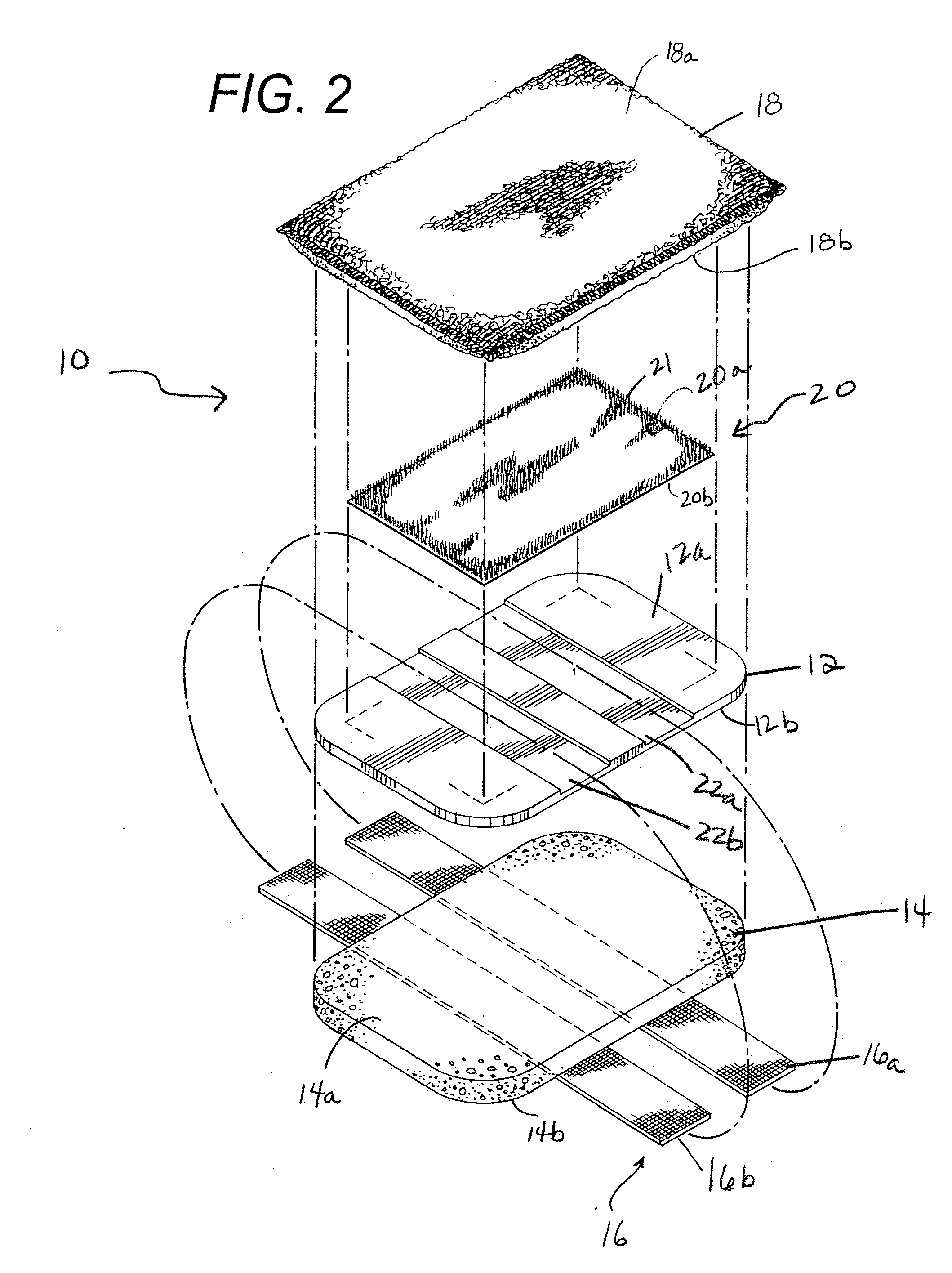
[0018]FIGS. 1-6 disclose a cleaning device of the present invention generally designated with the reference numeral 10. As shown in FIG. 2, the cleaning device 10 generally includes a base 12, a padded member 14, a strap assembly 16, a cleaning member 18, and a fastener 20.

[0019]As further shown in FIG. 2, the base 12 has a first side or top side 12a, and a second side or a bottom side 12b, and is comprised of a rigid material such as high density polyethylene or plastic. Another suitable material that may be utilized for the base 12 is Plexiglas synthetic resin. In one embodiment, ...


PUM


Abstract

A device for cleaning vehicle windshields assists in placing the user's hand in a favorable position to more easily clean the inside of a windshield with a wiping motion. The device includes a base having a padded member attached to its bottom side. A cleaning member is removably attached to the top side of the base. The device has straps that encircle the base and the padded member. The user's hand is placed through the straps such that the top side of the user's hand is against the bottom of the padded member. The user positions their hand to place the top side of the cleaning member against the windshield moving their hand in a wiping motion.

Description

RELATED APPLICATION[0001]The present application claims the benefit of and is a continuation-in-part of U.S. provisional application No. 60 / 822,283 filed Aug. 14, 2006, which application is expressly incorporated herein by reference.TECHNICAL FIELD[0002]The present invention generally relates to a device for cleaning vehicle windows and surfaces and in particular, a device for cleaning an inside surface of a vehicle windshield.BACKGROUND AND PRIOR ART[0003]Window cleaning devices are known in the art. Devices typically have a cloth-type surface or sponge for cleaning the window surface. While window cleaning devices according to the prior art provide a number of advantageous features, they nevertheless have certain limitations. For example, in certain environments, a window may have an angular configuration making cleaning more difficult. Vehicle windshields are one type of window wherein the angle of the windshield makes it difficult for one to clean the inside surface of the winds...

Claims


Application Information

Patent Timeline
IPC IPC(8): B25G1/00
CPCA47L1/15B60S3/045A47L13/18
Inventor PROBASCO, TIMOTHY PAUL
Owner PROBASCO TIMOTHY PAUL
Learn More