
Compressive Resistance Means and Exercise Device

a technology of compression resistance and exercise device, which is applied in the direction of muscle exercise device, gymnastic exercise, sport apparatus, etc., can solve the problems of difficult adjustment of resistance level, user's few options in changing resistance, and unwieldy use, etc., and achieve the effect of allowing adjustment of resistance level

Inactive Publication Date: 2012-08-23
JAHNS HENNER
View PDF16 Cites 22 Cited by
  • Summary
  • Abstract
  • Description
  • Claims
  • Application Information

AI Technical Summary

Benefits of technology

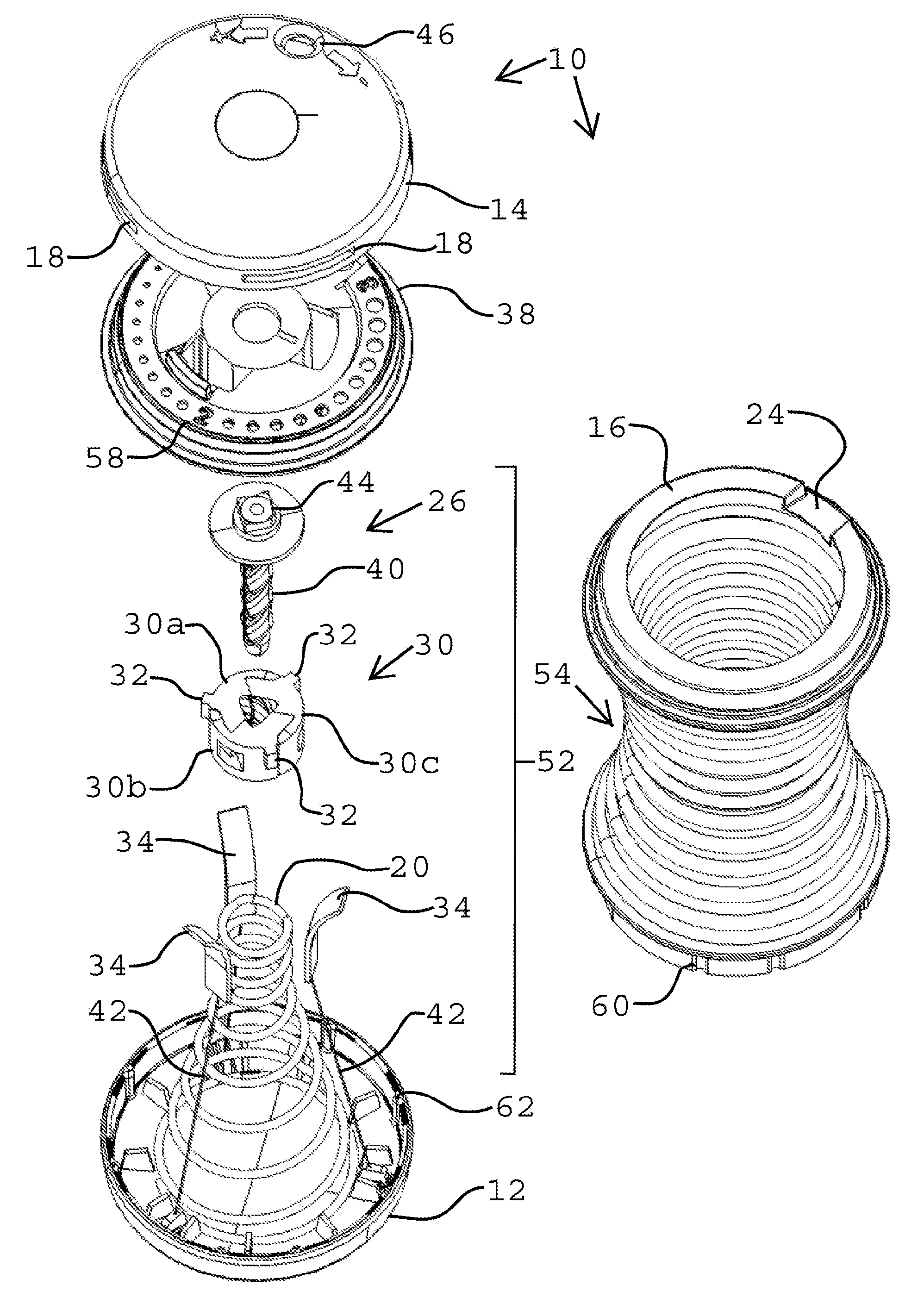
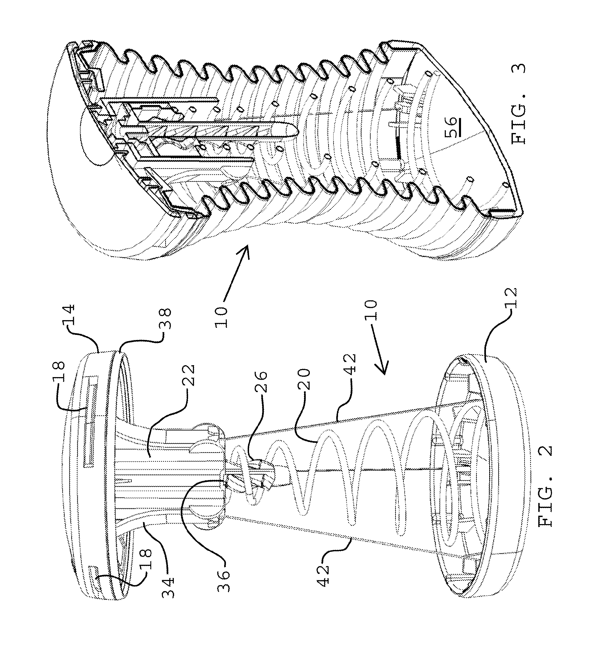
[0007]The present invention provides a unique exercise device that is compact and permits adjustment of the resistance level. The present invention can be made primarily of inexpensive injection molded plastic. Furthermore, the present invention provides up to three separate sources of resistance with adjustability in at least one. Also, the present invention provides the ability to compress and bend in a resistive manner.
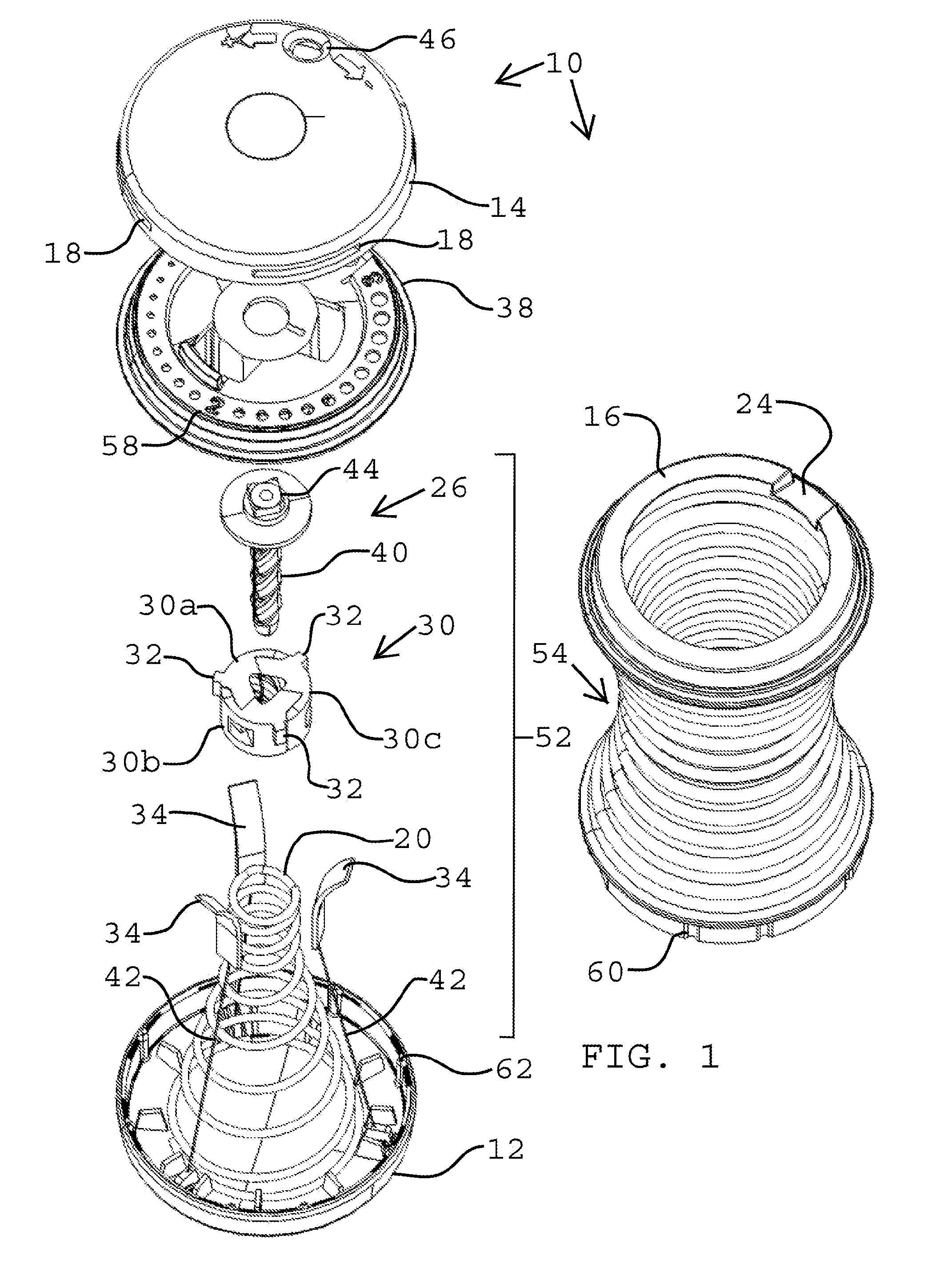
[0009]As is well known, a spring's resistance varies as a function of the distance it is deformed. When the spring is fully expanded, i.e., not compressed, then the initial force required to compress the exercise device is minimal. As the spring is compressed, the initial force required to further compress the spring by pushing the two ends together is substantially increased. In effect, the spring resistance is changed by changing the degree of initial compression due to the translating member bearing down on the spring. This adjustment permits the exercise device to maintain the same overall size and range of motion while just changing the spring deformation. The user simply rotates the twist cap until the desired resistance level is displayed through the window; then the base cap may be compressed towards the twist cap by overcoming the force of the resistance assembly.

Problems solved by technology

However, changing the resistance has been an issue with existing devices.
For example, if a coil spring is used as a resistance means, then the user has few options in changing the resistance.
However, this use often unwieldy and requires removable parts that are easily lost.
These devices are often complex and do not provide a large degree of adjustment.

Method used


Image

  • Compressive Resistance Means and Exercise Device
  • Compressive Resistance Means and Exercise Device
  • Compressive Resistance Means and Exercise Device

Examples


Embodiment Construction

[0017]exercise device 10

[0018]base cap 12

[0019]twist cap 14

[0020]sidewall 16

[0021]air vent 18

[0022]spring 20

[0023]guide 22

[0024]notch 24

[0025]rotating member 26

[0026]translating member 30

[0027]nut sections 30a, 30b, 30c

[0028]tab 32

[0029]limiting means 34

[0030]slot 36

[0031]stationary member 38

[0032]male thread 40

[0033]cord 42

[0034]head 44

[0035]window 46

[0036]resistance assembly 52

[0037]pleats 54

[0038]interior space 56

[0039]resistance markings 58

[0040]notch 60

[0041]extension 62

DESCRIPTION OF THE PREFERRED EMBODIMENTS

[0042]The detailed descriptions set forth below in connection with the appended drawings are intended as a description of embodiments of the invention, and is not intended to represent the only forms in which the present invention may be constructed and / or utilized. The descriptions set forth the structure and the sequence of steps for constructing and operating the invention in connection with the illustrated embodiments. It is to be understood, however, that the same o...


PUM


Abstract

An exercise device (10) is provided with a twist cap (14) spaced apart from a base cap (12) with a resistance assembly (52) therebetween. The resistance assembly (52) includes a spring (20), a rotating member (26) that rotates with the twist cap (14), and a translating member (30) threadably engaged to the rotating member (26) and configured to variably deform the spring (20) due to rotation of the twist cap (14) in order to adjust the resistance level. An annularly pleated sidewall (16) and a vent means (18) may be included to provide a further resistance means. The exerciser compresses the twist cap (14) towards the base cap (12) to experience both compressive and bending resistance.

Description

CROSS-REFERENCE TO RELATED APPLICATIONS [0001]This application claims the benefit of U.S. Provisional Patent Application 61 / 257,840 with a filing date of Nov. 4, 2009.BACKGROUND OF THE INVENTION [0002]1. Field of Invention[0003]The present invention relates generally to an exercise device and method, and more particularly, to a compressive exercising device and method for use thereof.[0004]2. Description of the Related Art[0005]Small exercise device that may be compressed by pushing two ends together is known in the art. These devices may use springs or other compressive resistance means to achieve sufficient resistance. However, changing the resistance has been an issue with existing devices. For example, if a coil spring is used as a resistance means, then the user has few options in changing the resistance. Some devices may permit the user to add or remove springs to change the resistance. However, this use often unwieldy and requires removable parts that are easily lost. Some de...

Claims


Application Information

Patent Timeline
Patent Type & Authority Applications(United States)
IPC IPC(8): A63B21/008A63B21/02
CPCA63B21/0004A63B21/00043A63B23/12A63B21/0455A63B21/05A63B21/023A63B21/4045
Inventor JAHNS, HENNER
Owner JAHNS HENNER
Learn More