Method for de-bonding flexible device

a flexible device and debonding technology, applied in the direction of identification means, instruments, seals, etc., can solve the problems of hindering the application of portable electronic products with light weight, poor impact resistance, thin and flexible frames

Inactive Publication Date: 2012-08-30
IND TECH RES INST
View PDF8 Cites 11 Cited by
  • Summary
  • Abstract
  • Description
  • Claims
  • Application Information

AI Technical Summary

Problems solved by technology

Glass displays have disadvantages such as fragility, poor impact resistance, heavy weight and being thick, thereby hindering application in portable electronic products with light weights, and thin and flexible frames.

Method used


Image

  • Method for de-bonding flexible device
  • Method for de-bonding flexible device
  • Method for de-bonding flexible device

Examples


Embodiment Construction

[0015]The following description is of a mode for carrying out the disclosure. This description is made for the purpose of illustrating the general principles of the disclosure and should not be taken in a limiting sense. The scope of the disclosure is best determined by reference to the appended claims. Wherever possible, the same reference numbers are used in the drawings and the descriptions to refer the same or like parts.

[0016]The present disclosure will be described with respect to particular embodiments and with reference to certain drawings, but the disclosure is not limited thereto and is only limited by the claims. The drawings described are only schematic and are non-limiting. In the drawings, the size of some of the elements may be exaggerated and not drawn to scale for illustrative purposes. The dimensions and the relative dimensions do not correspond to actual dimensions to practice of the disclosure.

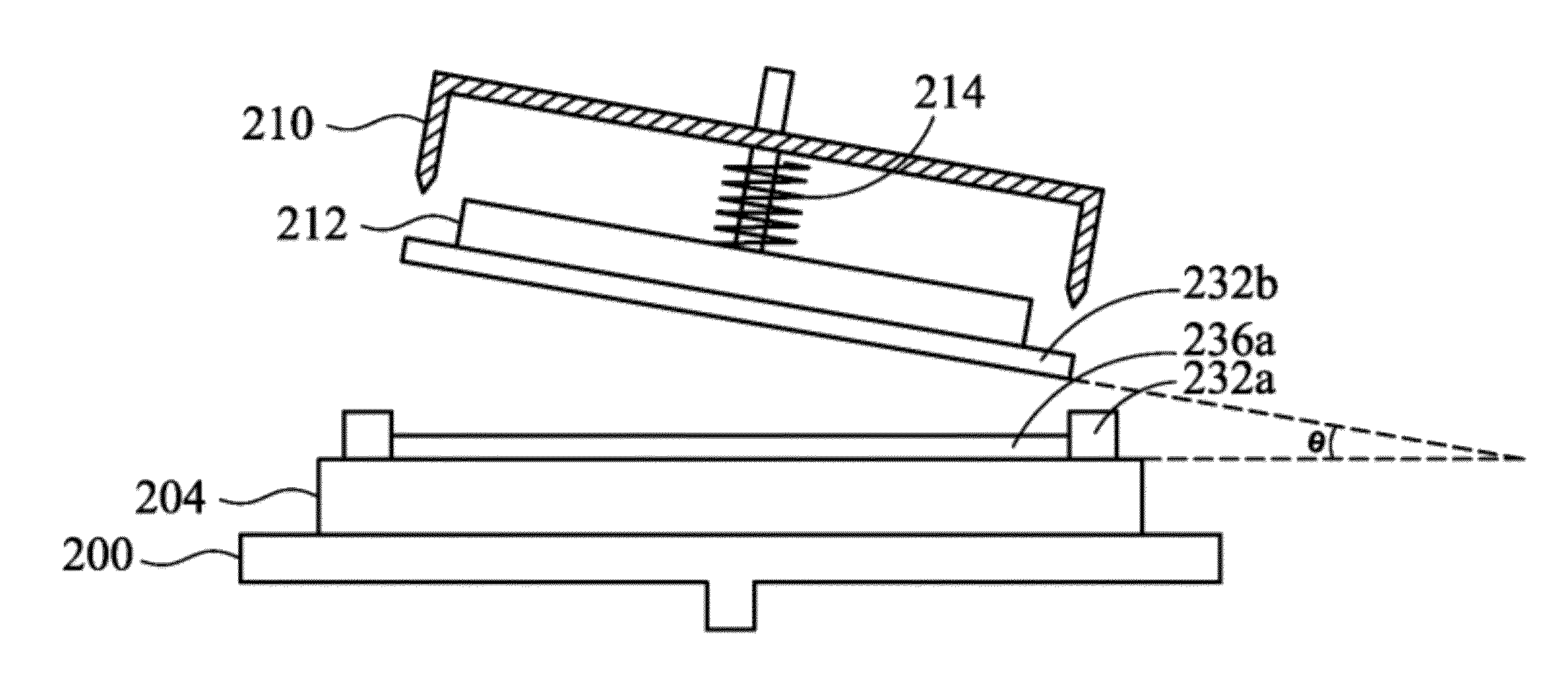
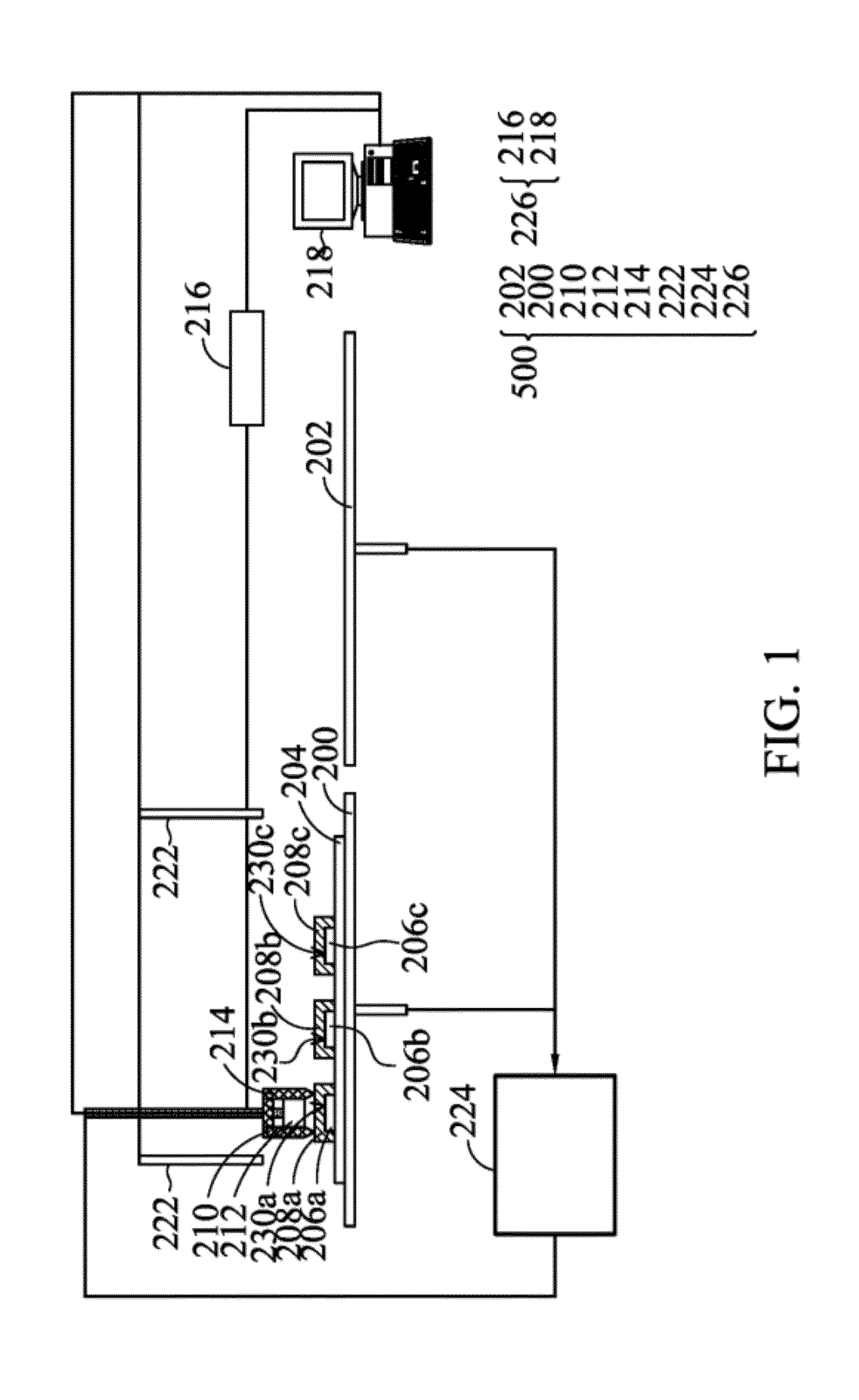
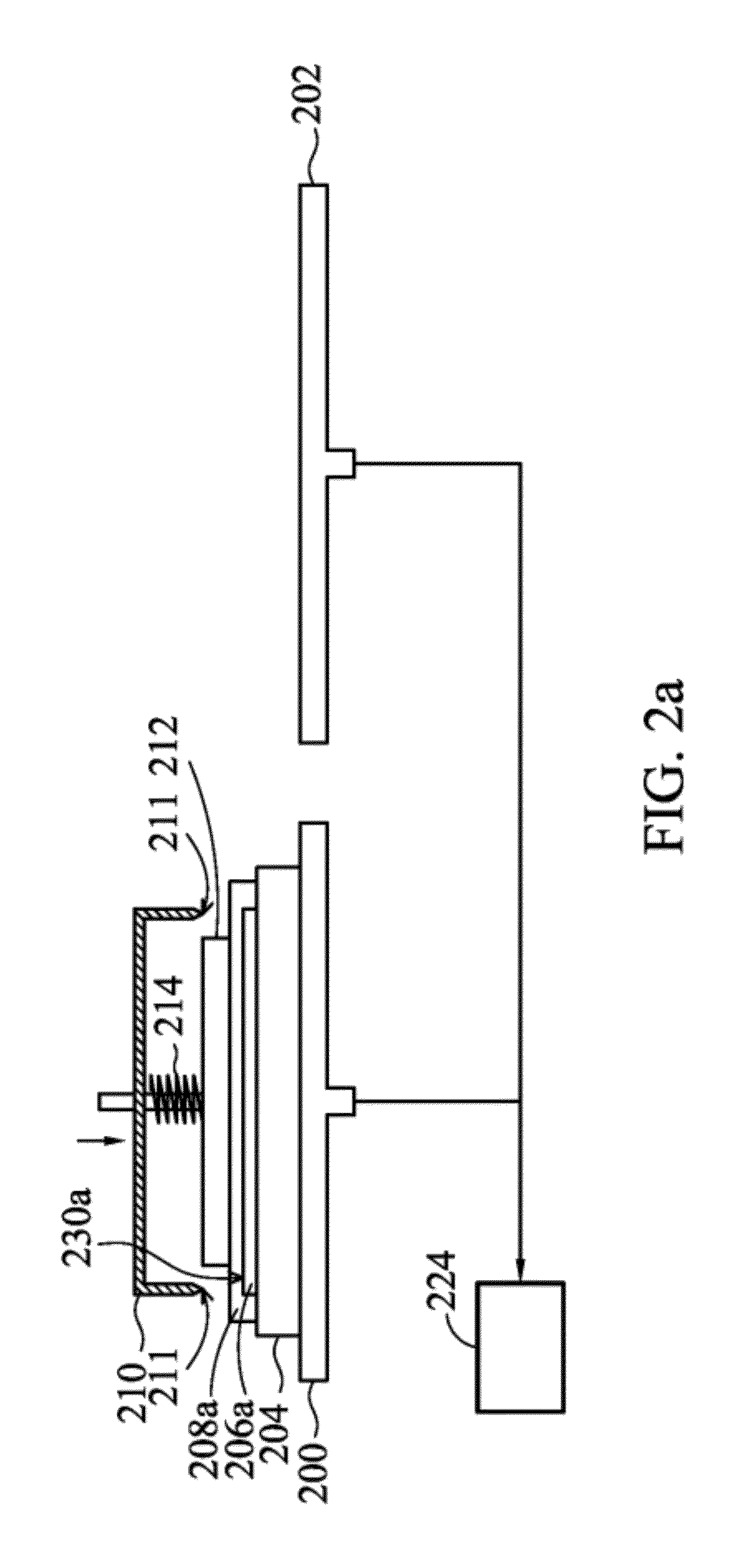
[0017]FIG. 1 is a schematic diagram showing one exemplary embodiment o...


PUM

PropertyMeasurementUnit
angleaaaaaaaaaa
angleaaaaaaaaaa
flexibleaaaaaaaaaa

Abstract

The disclosure provides a method for de-bonding a flexible device. The method for de-bonding a flexible device includes providing a first carrier to mount a carrier substrate thereon, a release layer thereon and a flexible device covering the release layer and a portion of the carrier substrate. A vacuum suction process is performed to suction the flexible device using a vacuum device. A separation process is performed with air entering into an interface between the flexible device and the release layer to separate a portion of the flexible device from the release layer and the carrier substrate using a separation device. A first release process is performed so that the portion of the flexible device is separated from the vacuum device.

Description

CROSS REFERENCE TO RELATED APPLICATIONS[0001]This application is a division of U.S. patent application Ser. No. 12 / 488,934, filed Jun. 22, 2009, which claims priority of Taiwan Patent Application No. 098107524, filed on Mar. 9, 2009, the entirety of which are incorporated by reference herein.BACKGROUND OF THE DISCLOSURE[0002]1. Field of the Disclosure[0003]The present disclosure relates to a method for de-bonding a flexible device, and in particular, to a method for de-bonding a flexible device disposed on a release layer.[0004]2. Description of the Related Art[0005]Glass displays have disadvantages such as fragility, poor impact resistance, heavy weight and being thick, thereby hindering application in portable electronic products with light weights, and thin and flexible frames. Thus, flexible substrates replacing glass displays have been disclosed, overcoming the disadvantages of glass displays and allowing increased design flexibility for shape and curl resultant of display pane...

Claims


Application Information

Patent Timeline
Patent Type & Authority Applications(United States)
IPC IPC(8): B32B38/10
CPCG02F1/1303G02F1/133305H01L21/67092G09F3/208Y10T156/1944Y10T156/1917Y10T156/1158Y10T156/1184Y10T156/1132Y10T156/1967
Inventor TSAI, PAO-MINGJIANG, LIANG-YOUCHANG, YU-YANG
Owner IND TECH RES INST
Why Eureka
Try Eureka