Lighting Device Comprising a Bulb

a technology of light source and bulb, which is applied in the direction of light source device, fixed installation, lighting and heating apparatus, etc., can solve the problems of reflexes and light spots, undesirable diffuse light effect of frosted lamps, etc., and achieve the effect of ensuring the exact positioning of the reflector in the bulb, convenient light distribution, and simple manufacturing

Inactive Publication Date: 2012-08-30
OSRAM GMBH
View PDF7 Cites 1 Cited by
  • Summary
  • Abstract
  • Description
  • Claims
  • Application Information

AI Technical Summary

Benefits of technology

[0007]By virtue of the bulb at least partially featuring a plurality of plane sections on at least one surface of the bulb, faceting is achieved at least in partial regions of the bulb; this results in narrowly delimited regions in which the light emerges from the bulb, while the adjacent region appears considerably darker. The light typically emerges approximately unidirectionally, and the main emission directions of the individual regions clearly differ from each other. As a result of this, firstly the desired sparkling brilliant impression is achieved directly at the lighting device, and secondly a surface-like light emission is avoided, such that this effect is also amplified in the light-refracting elements of a light fitting, for example, unlike lighting devices which comprise frosted bulbs. A plurality of plane sections is considered to exist when more than 5 sections (and in particular more than 10 sections) are present.
[0036]It can be generally advantageous if the main emission direction of the light source does not run parallel with the longitudinal axis of the lamp, since it is likewise possible thus to achieve a stronger lateral emission, wherein this can be advantageous particularly for use in a chandelier, since further light-refracting or reflective elements of the chandelier tend to be arranged to the side rather than above the lamp.

Problems solved by technology

The diffuse light effect of a frosted lamp is however undesirable in many applications, e.g. for use in a light fitting that comprises light-refracting elements such as a crystal chandelier, for example, wherein the observer is used to noticing both the incandescent filament itself, as a relatively concentrated light source within the glass bulb of the incandescent lamp, and a multiplicity of white and / or colored reflexes and light spots as a result of the refraction of the light on the crystal decorations of the chandelier, wherein these reflexes and light spots can change significantly due to a slight change in the perspective and / or viewing angle of the observer (sparkling, brilliant).

Method used


Image

  • Lighting Device Comprising a Bulb
  • Lighting Device Comprising a Bulb
  • Lighting Device Comprising a Bulb

Examples


Embodiment Construction

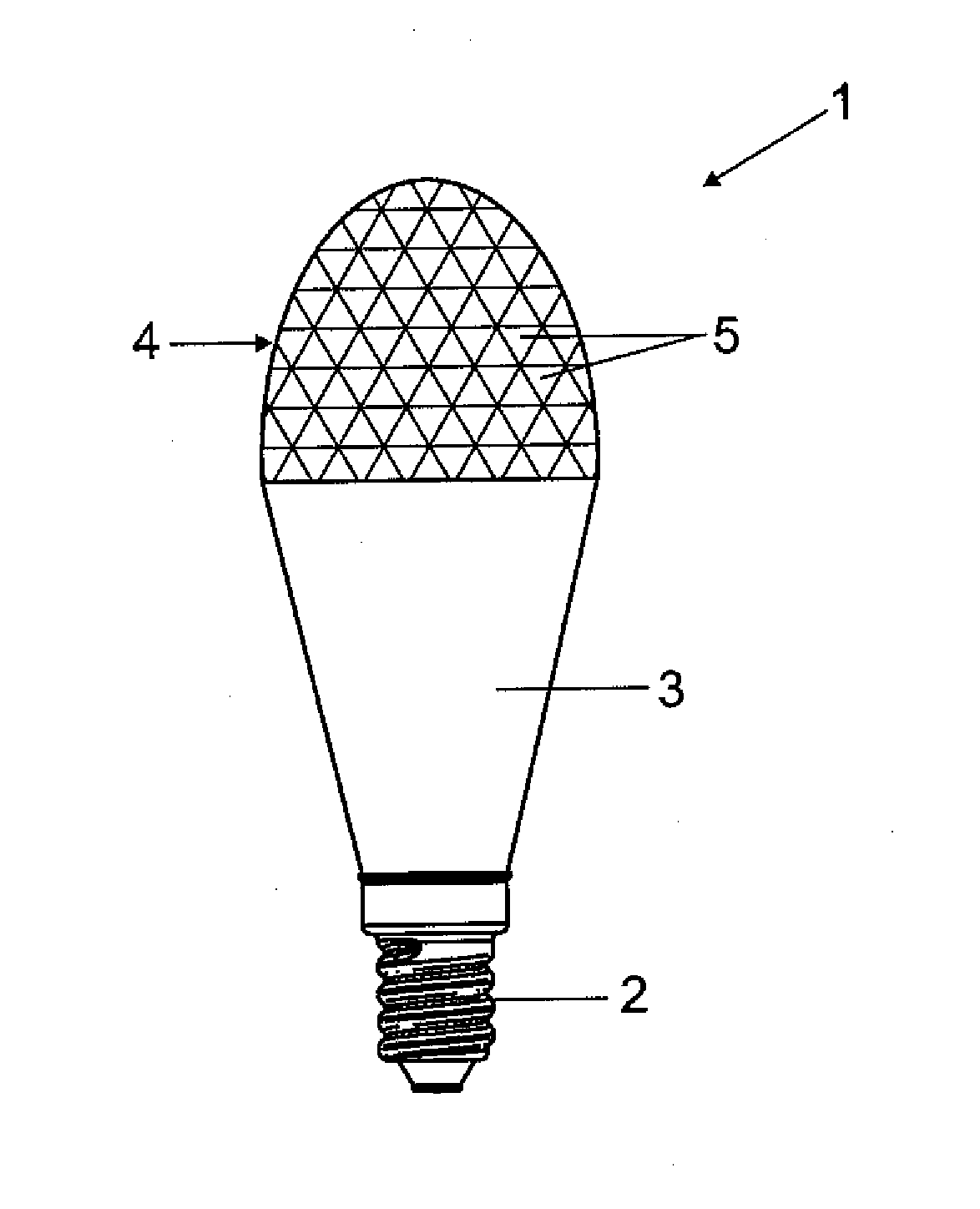
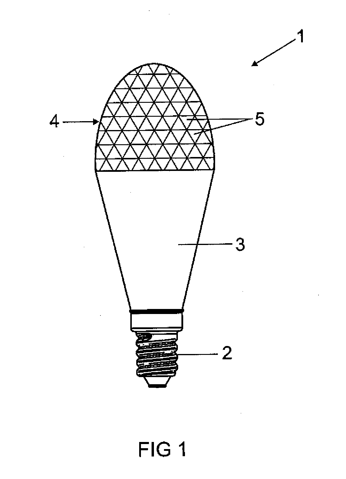
[0045]FIG. 1 shows a lighting device 1 according to the invention in a side view. A so-called retrofit lamp 1 is shown, i.e. a lighting device 1 that can be used in a standardized socket instead of a conventional incandescent lamp. Such lamps are intended to externally resemble an incandescent lamp as closely as possible, and therefore in addition to the standardized base 2 and a mounting piece 3, which is designed as a heat sink 3 here, provision is made for a bulb 4 that covers the actual light source. Unlike an incandescent lamp, where the bulb is fundamental to the function thereof, the bulb in retrofit lamps merely has, in addition to a decorative effect, the function of providing a protection of the light source against mechanical influences and a means of directing the beam. In contrast with the LED retrofit lamps disclosed in the prior art, in which the bulb is generally made of an opaque material, the bulb 4 shown in the exemplary embodiment is made of a transparent materia...


PUM


Abstract

A lighting device (1) comprising at least one light source (7), at least one at least partially transparent bulb (4) at least partially surrounding the at least one light source (7), and at least one base (2) for mechanically holding and electrically contacting the lighting device (1), wherein the bulb (4) at least partially features a plurality of plane sections (5) on at least one surface (11, 12) of the bulb (4).

Description

TECHNICAL FIELD[0001]The invention relates to a lighting device comprising at least one light source, at least one at least partially transparent bulb at least partially surrounding the at least one light source, and at least one base for mechanically holding and electrically contacting the lighting device.PRIOR ART[0002]Lighting devices of this type are used as so-called retrofit lamps for the purpose of replacing conventional incandescent lamps. The bulb is no longer used to protect the filament in this case, but is essentially for decorative purposes and / or directing the light. In the context of this application, a light source is therefore considered to be a device which is suitable for generating light and can be used continuously (i.e. at least for a plurality of hours) for general lighting purposes without further protective measures (i.e. a light source that also functions without a bulb, unlike the incandescent filament of an incandescent lamp). Since a transparent bulb all...

Claims


Application Information

Patent Timeline
Patent Type & Authority Applications(United States)
IPC IPC(8): F21V7/00F21V21/00F21V9/40
CPCF21S8/06F21V3/02F21W2121/00F21K9/135F21K9/50F21Y2101/02F21K9/232F21K9/60F21Y2115/10
Inventor BERTRAM, RALPHENGL, MORITZSCHWALENBERG, SIMON
Owner OSRAM GMBH
Why Eureka
Try Eureka