Pedal device for electronic percussion instrument

Active Publication Date: 2012-09-06
YAMAHA CORP
View PDF10 Cites 10 Cited by
  • Summary
  • Abstract
  • Description
  • Claims
  • Application Information

AI Technical Summary

Benefits of technology

[0012]The present invention has been made to solve the conventionally experienced problem. It is therefore an object of the invention to provide a ped

Problems solved by technology

Since a change of the expansion amount of the tension coil spring is larger than a change of the pivot angle of the foot board, however, the spring constant of the tension coil spring that actually acts on the foot board is large, so that the force becomes nonlinear.
As a result, in spite of the fact that the foot of the player is already r

Method used


Image

  • Pedal device for electronic percussion instrument
  • Pedal device for electronic percussion instrument
  • Pedal device for electronic percussion instrument

Examples


first modified embodiment

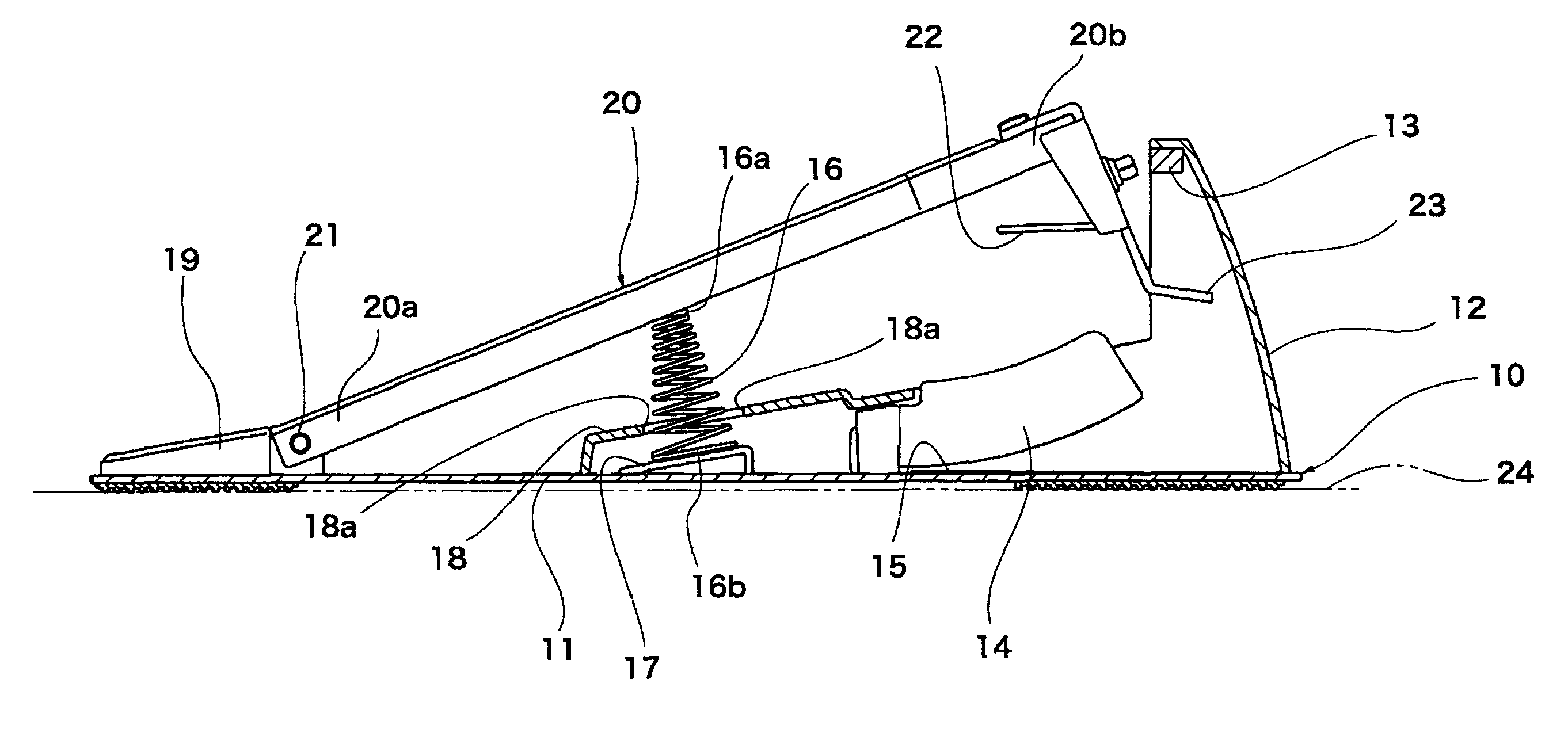
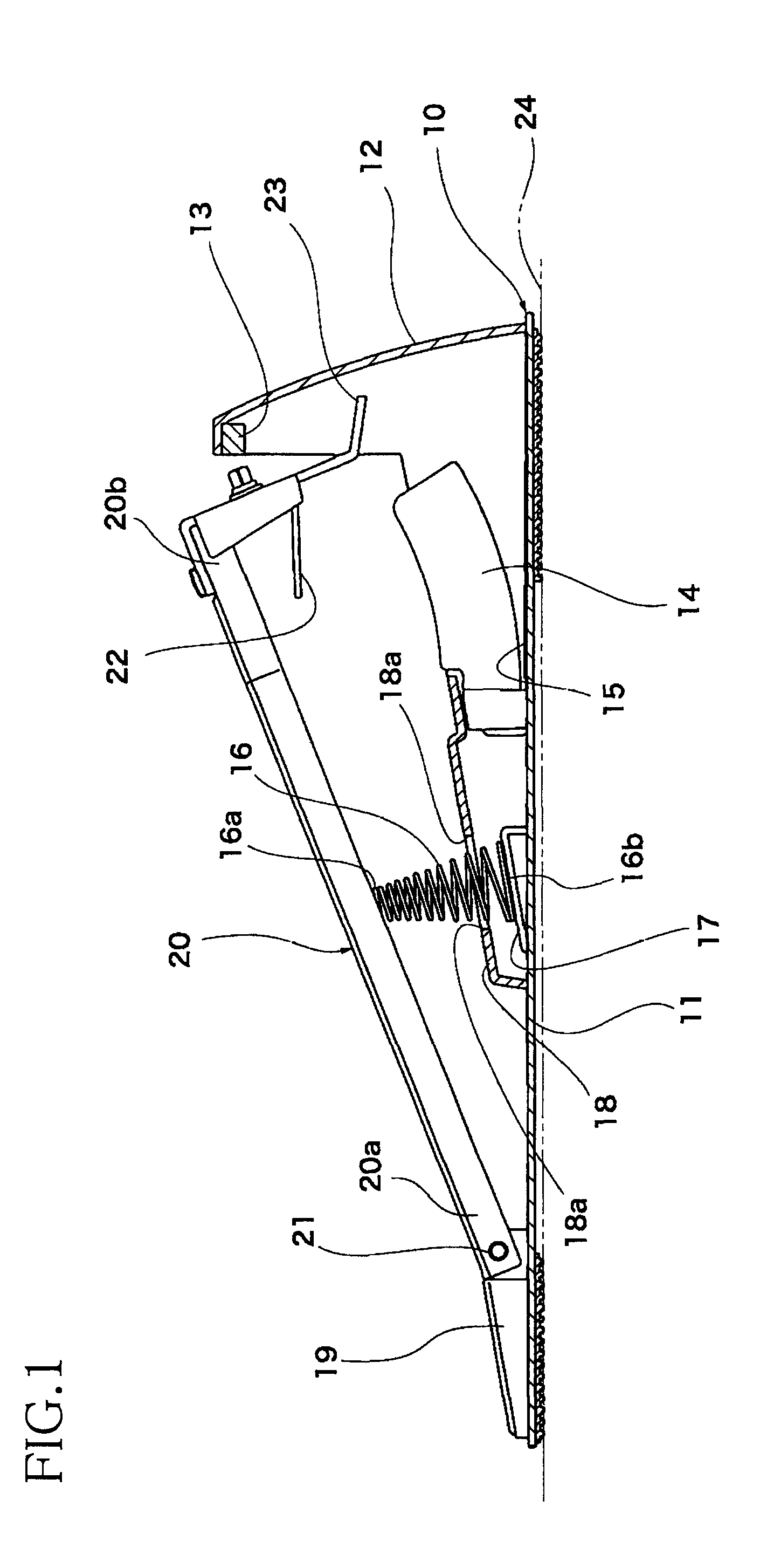
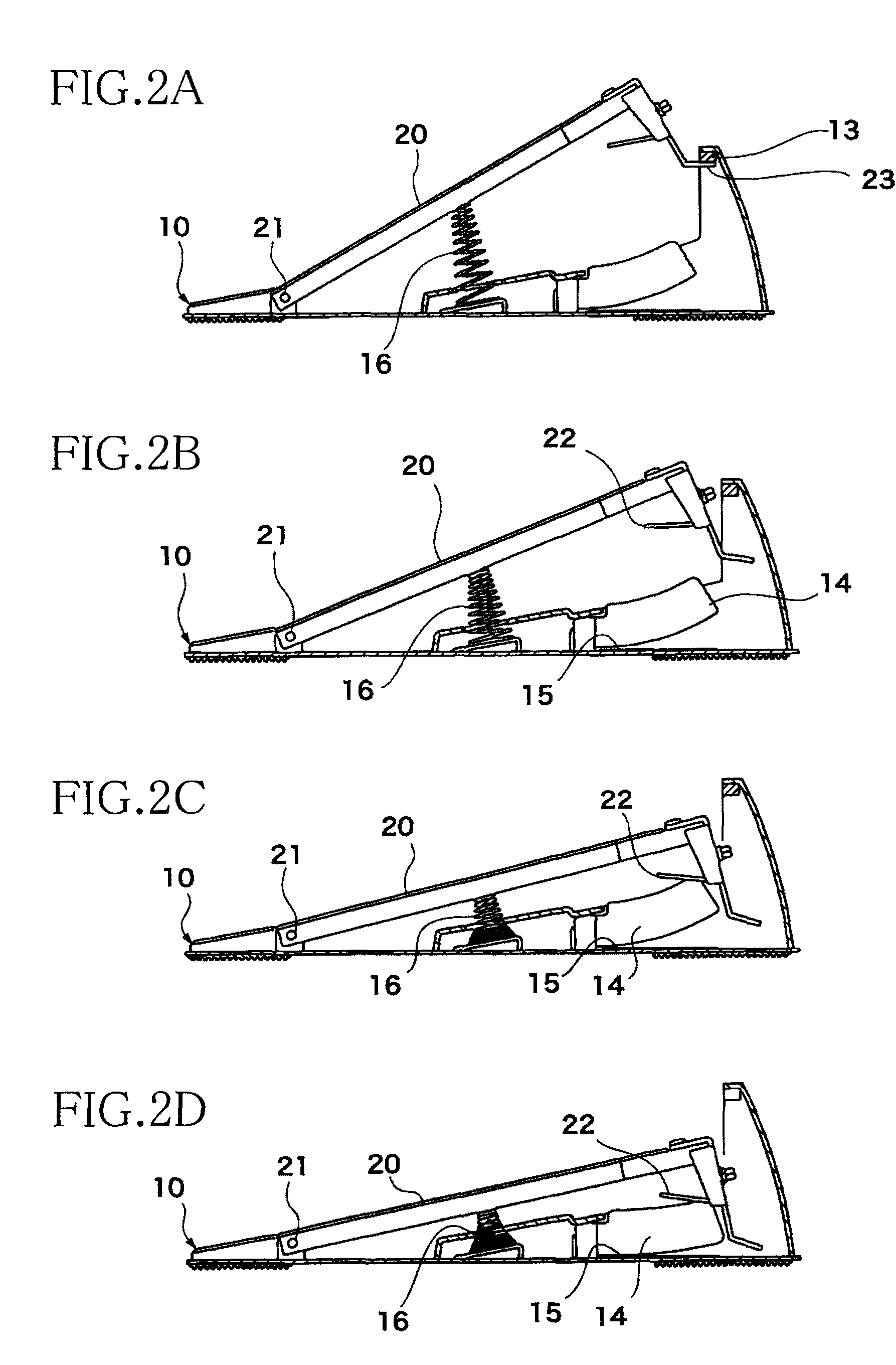
[0051]In the first modified embodiment shown in FIG. 4A, two coil springs, i.e., a first coil spring 31 as a first elastic member and a second coil spring 32 as a second elastic member, are used in place of the coil spring 16 used in the illustrated embodiment. The coil springs 31, 32 are disposed at the spring support portion 17 so as to pass through the hole 18a formed in the spring cover portion 18. Each of the coil springs 31, 32 is not conical, but has a cylindrical shape and has a coil portion whose outside diameter is constant over the entire length. The first coil spring 31 is fixed to both of the lower surface of the foot board 20 and the spring support portion 17. The second coil spring 32 is fixed at its lower end to the spring support portion 17, and an upper end of the second coil spring 32 is not fixed to any member. The pedal device of FIG. 4A is similar in construction with the pedal device of FIG. 1 except the above.

[0052]In the thus constructed pedal device, when t...

second modified embodiment

[0059]In this second modified embodiment, for obtaining the return force having the nonlinear characteristic in the entire range from the initial position to the lower limit position, the buffer member 34 may be fixed to the limit plate 23. Further, the coil spring 33 may be constructed so as to be fixed to the limit plate 23 via the buffer member 34, without being fixed to the underside of the ceiling part of the rear portion of the cover 12. In such a configuration, the characteristic of the return force with respect to the change of the pivot angle of the foot board 20 can be made similar to that in the illustrated embodiment of FIG. 1. Further, as in the illustrated embodiment of FIG. 1, the upper end 16a of the coil spring 16 may be fixed to the foot board 20.

third modified embodiment

[0060]FIG. 4C shows a pedal device according to the The pedal device of FIG. 4C is constructed such that a leaf spring 35 is disposed in place of the coil spring 16 in the pedal device of FIG. 4B. Illustration of the coil spring 33, the buffer member 34, the limit plate 23, etc., is omitted. In the pedal device of FIG. 4C, a support base 36 is fixed onto the base portion 11. One end of the leaf spring 35 is supported at a first pivot point P1 of the support base 36, as if the leaf spring 35 acts like a cantilever, and a free end of the leaf spring 35 is in pressing contact with the lower surface of the foot board 20 so as to be slidable thereon. A portion of the upper surface of the support base 36 from the first pivot point P1 to a second pivot point P2 which is located forward of the first pivot point P provides a flat surface, and a portion of the upper surface of the support base 36 which is located frontward of the second pivot point P2 provides a curved surface that is convex...


PUM


Abstract

A pedal device for an electronic percussion instrument, including: a base; a foot board pivotable in a pivotable range between lower and upper limit positions; and an elastically holding mechanism for holding the foot board such that the foot board keeps an equilibrium state at an initial position within the pivotable range, the foot board being configured such that (a) when the foot board is located between the initial and the upper limit positions, it is given by the mechanism a return force having a linear characteristic with respect to a change of its pivot angle, the return force being for permitting the foot board to return to the initial position, and (b) when the foot board is located between the initial and the lower limit positions or between: an intermediate position and the lower limit position, the foot board is given the return force having a nonlinear characteristic.

Description

CROSS REFERENCE TO RELATED APPLICATION[0001]The present application claims priority from Japanese Patent Application No. 2011-044867, which was filed on Mar. 2, 2011, the disclosure of which is herein incorporated by reference in its entirety.BACKGROUND OF THE INVENTION[0002]1. Field of the Invention[0003]The present invention relates to a pedal device for an electronic percussion instrument.[0004]2. Discussion of Related Art[0005]A pedal device for an electronic percussion instrument is known. In the pedal device described in the following Patent Literature 1, a foot board is pivotably supported on a base plate (a base), and a weight is provided at a free end of the foot board. Further, a tension coil spring is provided at the free end of the foot board. The known pedal device aims at achieving a depression feeling close to that in an acoustic drum owing to an inertial force by the weight and a load increase by the tension coil spring at a time when the foot board is depressed or s...

Claims


Application Information

Patent Timeline
IPC IPC(8): G10H1/32
CPCG10H2230/275G10H1/348
Inventor HASHIMOTO, RYUJI
Owner YAMAHA CORP
Why Eureka
Try Eureka