Bush cutter and protective cover for the same

a bush cutter and protective cover technology, applied in the field of bush cutters and protective covers, can solve the problems of easy pushed with tools, unstable posture of the bush cutter, and easy breakage of the click portion

Inactive Publication Date: 2012-09-13
MAKITA CORP
View PDF10 Cites 15 Cited by
  • Summary
  • Abstract
  • Description
  • Claims
  • Application Information

AI Technical Summary

Benefits of technology

[0010]Preferably, one of the main body and the expansion part of the protective cover may be provided with a contact portion configured to contact with the click portion from inside when the click portion is pushed out from the engaging hole with the tool. According to this structure, even if the user pushes the click portion strongly with a tool, the click portion does not deform excessively and breakage of the click portion can be prevented.
[0011]Preferably, the bush cutter relating to the present teachings may comprise an operation pole including a tip end on which the cutting blade is disposed, and a protective bar extending from the operation pole and configured to be located in front of a user when the user holds the bush cutter. In this case, the click portion engaging with the engaging hole and the protective bar provided on the operation pole may preferably be located at a same side with

Problems solved by technology

In a bush cutter of this type, when the cutting blade is changed for one of a different size and/or type, the size of the protective cover does not match the

Method used


Image

  • Bush cutter and protective cover for the same
  • Bush cutter and protective cover for the same
  • Bush cutter and protective cover for the same

Examples


Embodiment Construction

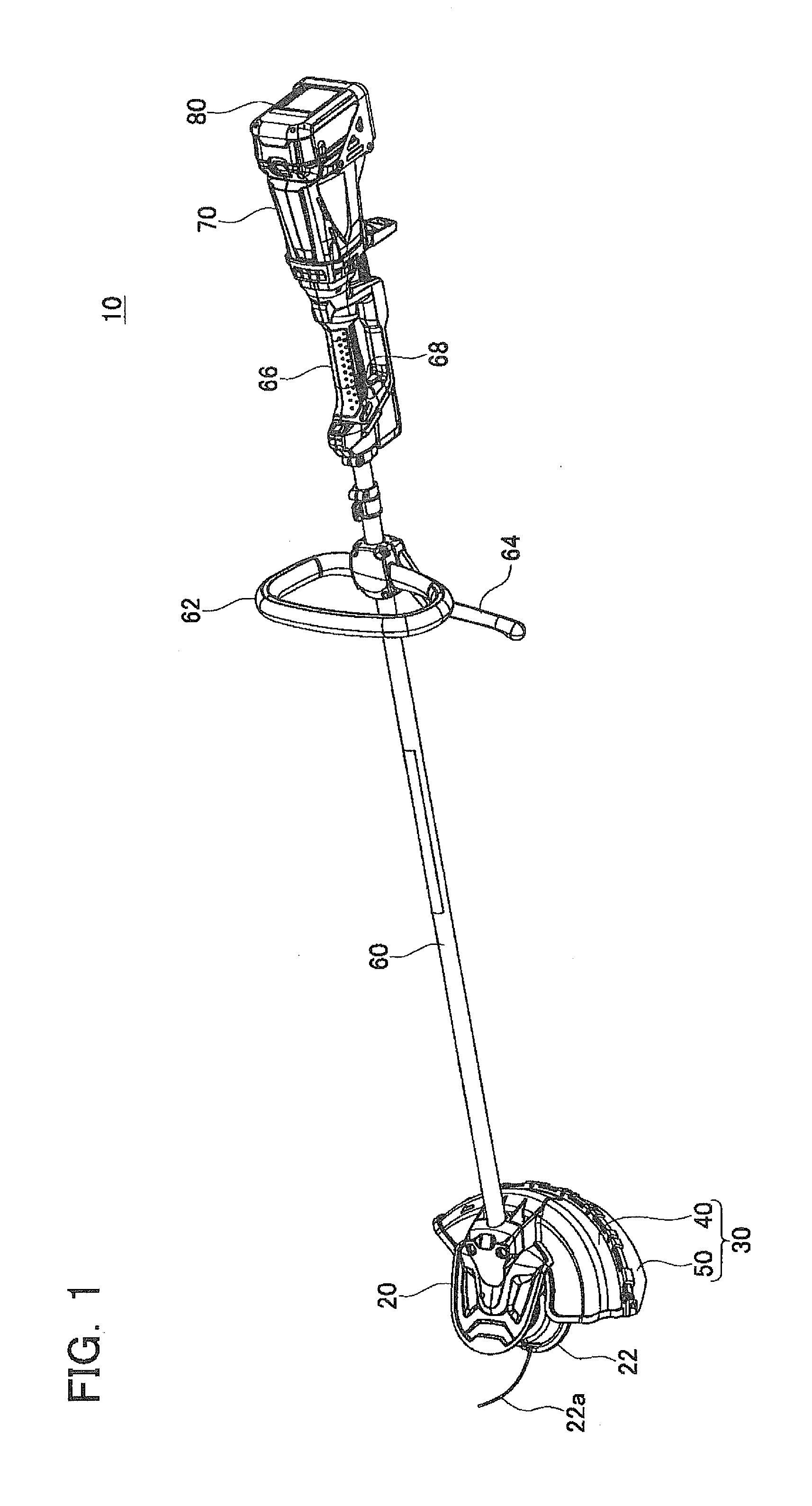
[0022]A bush cutter 10 according to an embodiment is described here with reference to the drawings. The bush cutter 10 is one type of motorized gardening tool which is used generally for cutting grass. As shown in FIG. 1, the bush cutter 10 comprises: an operation pole 60, a cutting blade unit 20 provided on an anterior end of the main pole 60, and a motor unit 70 provided on a posterior end of the operation pole 60. A battery pack 80 is installed detachably in the motor unit 70.

[0023]The operation pole 60 is a hollow pipe member. A rotating shaft (not illustrated) which extends from the motor unit 70 to the cutting blade unit 20 is provided inside the operation pole 60. The rotating shaft is driven so as to rotate by the motor unit 70 and transmits torque from the motor unit 70 to the cutting blade unit 20.

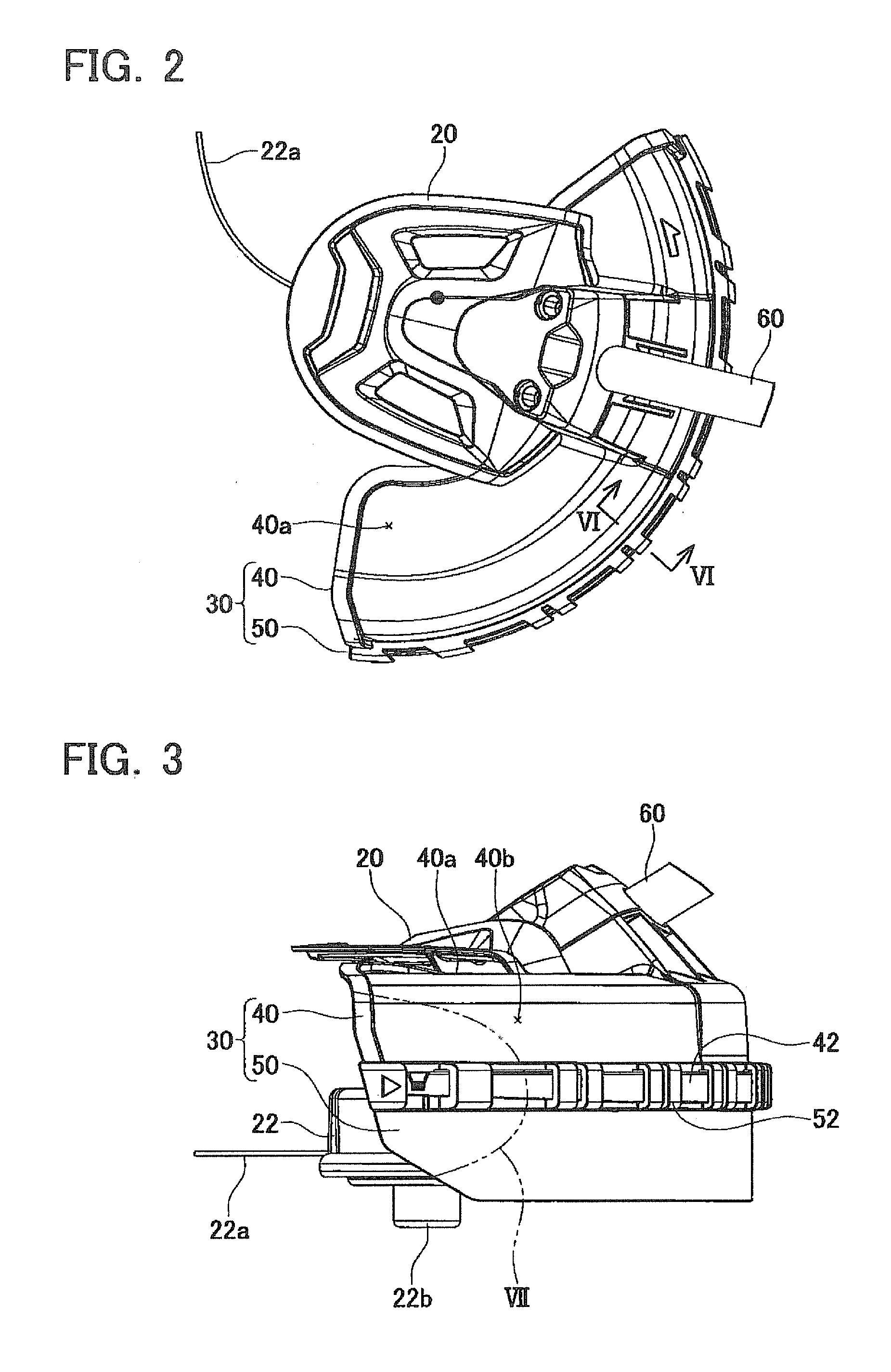
[0024]The cutting blade unit 20 comprises a cutting blade 22 and a protective cover 30. The cutting blade 22 is installed detachably on the cutting blade unit 20. The cutting bla...


PUM


Abstract

A bush cutter is provided with a cutting blade and a protective cover configured to partly cover the cutting blade. The protective cover includes a main body and an expansion part configured to be detachably attached to the main body. One of the main body and the expansion part of the protective cover is provided with a click portion and the other is provided with an engaging hole configured to accept engagement of the click portion from an inner side and expose the engaging click portion to an outer side. The engaging hole has an aperture geometry that allows entry of a tool but prevents entry of a fingertip. Accordingly, no tool is required when attaching the expansion part, but at least one tool is required when detaching the expansion part.

Description

TECHNICAL FIELD[0001]The present teachings relates to a bush cutter and a protective cover for the same.DESCRIPTION OF RELATED ART[0002]A bush cutter which cuts grass and bushes is commonly known. The bush cutter is provided with a cutting blade which rotates and a protective cover which partially covers the cutting blade. In a bush cutter of this type, when the cutting blade is changed for one of a different size and / or type, the size of the protective cover does not match the cutting blade and the cutting blade may interfere with the protective cover, or the cutting blade may be exposed more than necessary from the protective cover.[0003]In relation to the problem described above, Japanese Patent Application Laid-open No. 2001-333616 and U.S. Pat. No. 4,864,728 disclose a bush cutter which is configured in such a manner that a portion of a protective cover is detachably attached. In this bush cutter, the protective cover is provided with a main body and an expansion part, and the ...

Claims


Application Information

Patent Timeline
IPC IPC(8): B26B29/00
CPCA01D34/4167A01D34/90A01D34/828A01D75/206
Inventor ITO, RYOSUKEKONDO, MASAKI
Owner MAKITA CORP
Why Eureka
Try Eureka