Fire Detection

a technology for fire detection and fire fronts, applied in fire alarms, fire alarm electric actuators, instruments, etc., can solve the problems of inability to view by air, affecting the accuracy of fire front information, and affecting the direction and speed of fire,

Active Publication Date: 2012-09-13
ATTENTIS PTY LTD
View PDF9 Cites 65 Cited by
  • Summary
  • Abstract
  • Description
  • Claims
  • Application Information

AI Technical Summary

Benefits of technology

[0010]According to one aspect of the invention there is provided A sensor unit comprising a heat resistant shell, the shell having a plurality of viewing windows spaced around the shell exterior, each viewing window being optically coupled to a sensor within the shell that optically senses fire, the interior of the shell defining a chamber containing at least one smoke detector, and a temperature sensor mounted on or in the unit, the shell housing a radio transmitter arranged to transmit signals actuated by one or more of the fire sensor, smoke detector or temperature sensor.

Problems solved by technology

Wildfires (Bushfires) are an increasing threat throughout all areas around the globe having devastating effects including loss of human lives, wildlife, structure loss and are costing billions of dollars each year to contain, extinguish and rebuild the lost property as well as psychological effects to those directly affected by such fires.
Once the fire is underway, information about the fire front, including exact location, size of the front, direction and speed becomes hampered by smoke and poor visibility and cannot be viewed by air.
Aerial surveillance of the overall wildfire area is often covered by dense smoke, limited visibility and provides insufficient information regarding the actual position of the fire front.
Such sightings are limited to daylight hours and involve a sighting of smoke from an aircraft or land-based person.
However due to the fact that satellites are constantly moving, detection is limited because a satellite passing over a specific area can be as infrequent as twice per day.
The limitations of camera systems is that they are only useful during the daylight hours, require human intervention to determine the image and fail to provide the exact location of the fire source as they have a limited ability to pin point the location with a 5 mile radius.
The limitations using this type of system of detection is that aircraft rarely operate at night, flight times and manpower is expensive and limited to one area at a time—only the area currently being covered by the aircraft.

Method used


Image

  • Fire Detection
  • Fire Detection
  • Fire Detection

Examples


Embodiment Construction

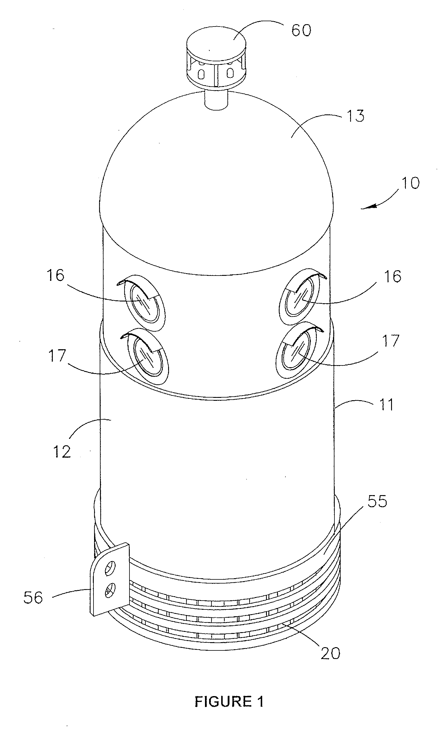
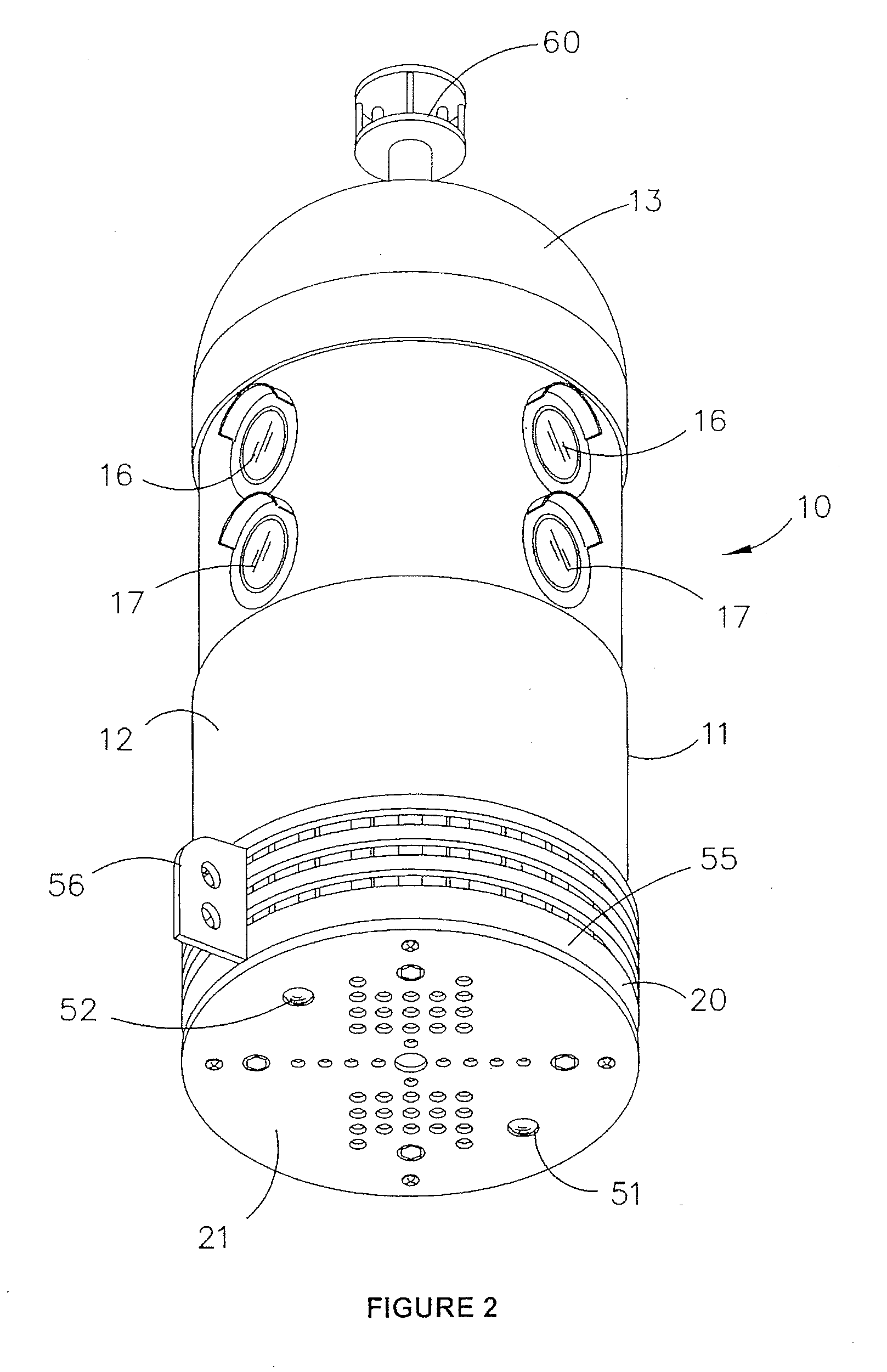
[0024]The sensor unit 10 illustrated in the accompanying drawings is manufactured in heat resistant plastics and essentially comprises an outer shell 11 with a cylindrical main body 12 and domed head 13. The shell 11 sits on top of a base structure 20 that comprises a base plate 21 that supports a platform 22 half way up the sensor unit 10 on three equally spaced pillars 23. The base plate 21 and platform 22 are designed to support the componentry that makes up the sensor unit 10.

[0025]The sensor 10 has been designed to have at least 12 different individual sensors which are described hereunder. Four infrared pyroelectric viewing sensors 25, 26, 27, 26 and four infrared thermopile sensors 30, 31, 32, 33 are housed within similarly shaped central housings 40 that are supported on a vertical column 41 with each pyroelectric sensor 25-28 being positioned above the thermopile sensor 30-34. The outward extremity of each housing is covered by a Fresnel lens 42. The column 41 comprises an ...


PUM


Abstract

A sensor unit comprising a heat resistant shell, the shell having a plurality of viewing windows spaced around the shell exterior to define a 360° view around the unit, each viewing window being optically coupled to an infrared pyroelectric sensor and an infrared thermopile sensor, the interior of the shell defining a chamber containing at least two different smoke detectors, the shell having ventilation holes communicating with the chamber and temperature sensors mounted on the unit, the shell housing at least one printed circuit board coupled to the sensors and detectors and supporting a computer and radio transmitter, and a rechargeable power source powering the printed circuit board.

Description

[0001]This invention relates to fire detection and in particular relates to a sensor unit for use in detecting fire and a communication system that incorporates a plurality of sensor units.BACKGROUND OF THE INVENTION[0002]Wildfires (Bushfires) are an increasing threat throughout all areas around the globe having devastating effects including loss of human lives, wildlife, structure loss and are costing billions of dollars each year to contain, extinguish and rebuild the lost property as well as psychological effects to those directly affected by such fires.[0003]The entire world, specifically the United States, Australia, Italy, France, China, Russia, Israel, and Greece experience major wildfires, so a cost effective solution must be sought to prevent the major increase in wildfires throughout the decades.[0004]Current methods of detection are through visual means and only alert emergency services once the fire has consumed a vast parcel of land. Once the fire is underway, informati...

Claims


Application Information

Patent Timeline
Patent Type & Authority Applications(United States)
IPC IPC(8): G08B17/00
CPCG08B17/06G08B17/10G08B29/183G08B25/10G08B17/125G08B17/113
Inventor MCKENNA, CAMERON
Owner ATTENTIS PTY LTD
Why Eureka
Try Eureka