
Triggers to Fault Information Insertion in Optical Transport Network

a technology of optical transport network and trigger, applied in the field of communication systems, can solve problems such as loss of communication between nodes in the network, and achieve the effect of reducing or eliminating the disadvantages and problems associated with previous techniques for communication of fault information in optical network

Inactive Publication Date: 2012-09-13
FUJITSU LTD
View PDF5 Cites 21 Cited by
  • Summary
  • Abstract
  • Description
  • Claims
  • Application Information

AI Technical Summary

Benefits of technology

[0004]In accordance with the present disclosure, disadvantages and problems associated with previous techniques for communication of fault information in an optical network may be reduced or eliminated.

Problems solved by technology

Faults may disrupt the traffic transported along the communication networks and cause a loss of communication between nodes in the networks.

Method used


Image

  • Triggers to Fault Information Insertion in Optical Transport Network
  • Triggers to Fault Information Insertion in Optical Transport Network
  • Triggers to Fault Information Insertion in Optical Transport Network

Examples


Embodiment Construction

[0012]Embodiments of the present disclosure and its advantages are best understood by referring to FIGS. 1-4, where like numbers are used to indicate like and corresponding parts.

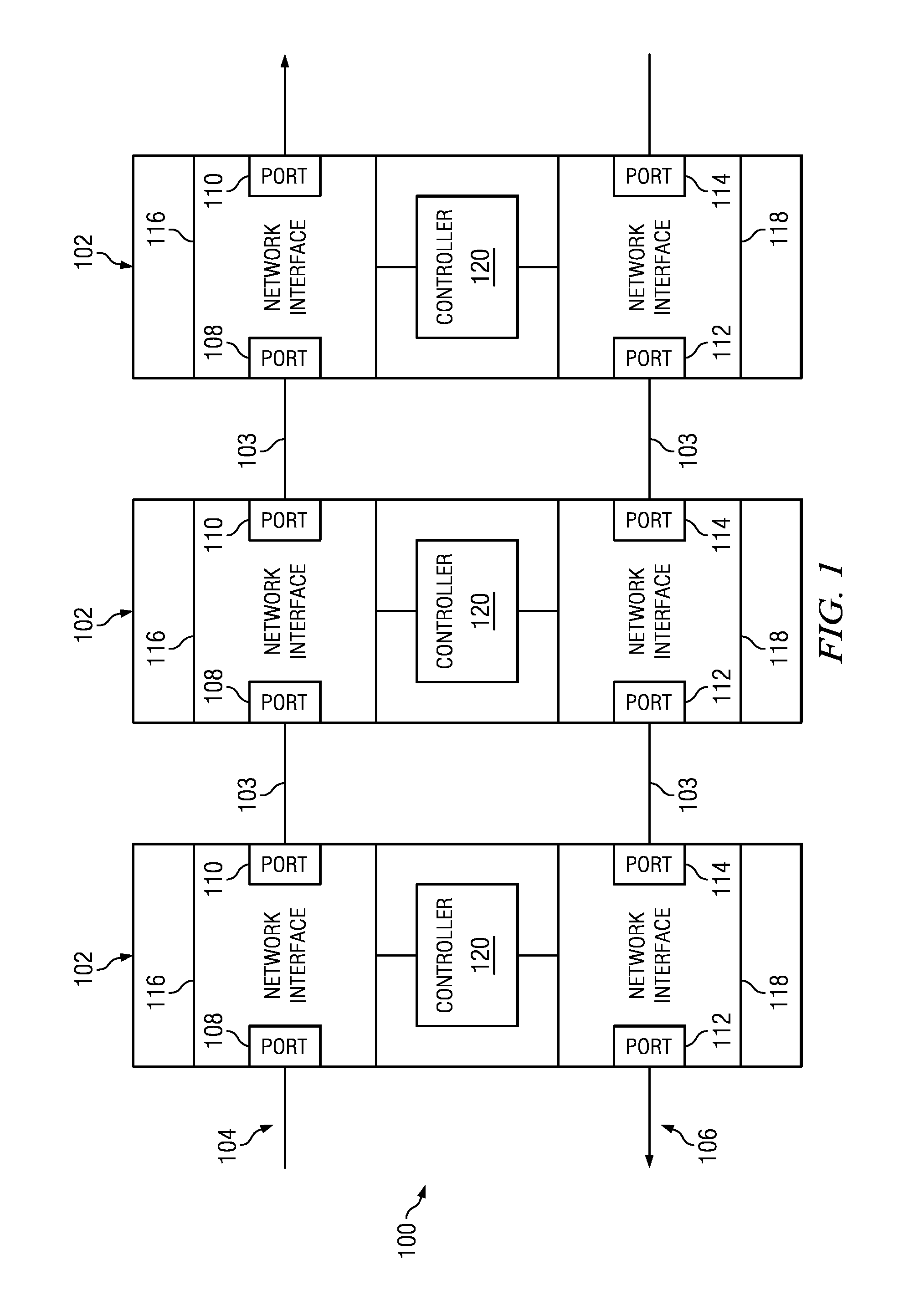
[0013]FIG. 1 illustrates an embodiment of a system 100 configured to transmit data or signals within a network, in accordance with embodiments of the present disclosure. A communication network may include nodes and transmission media that facilitate communication between nodes within the network. The communication of signals or data between and within nodes may be referred to as “traffic.”

[0014]In some embodiments the nodes may be network elements 102 that receive or transmit traffic within the network. Transmission media 103 may be configured to couple network elements 102 and carry traffic between network elements 102.

[0015]Faults or errors may occur in transmission media 103 or network elements 102 and the faults may disrupt traffic within the network. Network elements 102 may be configured to detect an...


PUM


Abstract

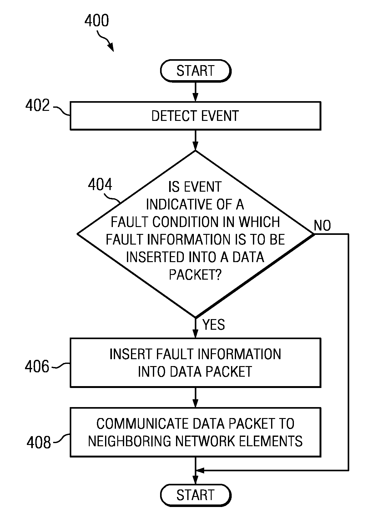
Systems and methods for triggering fault information insertion in an optical network are disclosed. In accordance with certain embodiments of the present disclosure, a method may include detecting, by a network element, occurrence of an event. The network element may also determine whether the event comprises a triggering fault condition in which fault information is to be communicated. The network element may additionally insert fault information into a data packet. The network element may further communicate the data packet to at least one neighboring network element.

Description

RELATED APPLICATION[0001]This application is related to co-pending U.S. patent application Ser. No. 12 / 779,601, filed May 13, 2010, and titled “Identifying Fault Locations in a Network,” which is incorporated by reference herein.TECHNICAL FIELD[0002]The present invention relates generally to the field of communication systems and more specifically to insertion of fault information in an optical transport unit in an optical network.BACKGROUND OF THE INVENTION[0003]Communication networks are typically configured to detect faults within the networks. Faults may disrupt the traffic transported along the communication networks and cause a loss of communication between nodes in the networks. Communication networks seek to isolate the faults in a timely manner to avoid losses of data and to maintain communication within the network.SUMMARY OF THE INVENTION[0004]In accordance with the present disclosure, disadvantages and problems associated with previous techniques for communication of fau...

Claims


Application Information

Patent Timeline
IPC IPC(8): H04B10/08H04L12/26
CPCH04J2203/006H04J3/14
Inventor YUAN, CATHERINE HAIYANTIEU, QUANG CHANSOLOMON, DAVIDMITTAL, VIKASLYON, DANIEL P.
Owner FUJITSU LTD
Learn More