
printer

Active Publication Date: 2012-09-13
SEIKO EPSON CORP
View PDF3 Cites 1 Cited by
  • Summary
  • Abstract
  • Description
  • Claims
  • Application Information

AI Technical Summary

Benefits of technology

[0006]An advantage of some aspects of the invention is to be able to suppress the transfer of a coloring agent to a roller in a type of printer in which it is necessary to fix the coloring agent to the printing medium.
[0008]That is, it takes a lot of time to complete printing in a printer in which the printing medium after the printing is transported in the direction opposite to the transport direction (forward direction), and is printed again at the time of printing, when the printer has a configuration in which the printing medium is transported to the opposite direction after waiting until the coloring agent is sufficiently fixed to the printing medium. Therefore, when the printer has a configuration in which the printing medium is transported to the opposite direction before the coloring agent is sufficiently fixed to the printing medium in order to perform the printing at a high speed, there is a problem in that a transfer of the coloring agent occurs in the roller. However, in the invention, when executing the reverse transport control in which the printing medium is transported to the direction opposite to the transport direction at the time of printing, the printing medium is transported in a state where a load smaller than a load which is applied when executing the forward transport control at the time of printing is applied to the printing medium by the roller. Accordingly, it is possible to suppress the transfer of the coloring agent with respect to the roller.
[0014]In this manner, in a state where the back tension is applied to the printing medium in the forward transport control, and the back tension is not applied to the printing medium in the reverse transport control, it is possible to transport the printing medium while easily maintaining a desired transport accuracy, even if, in the reverse transport control, the load applied to the printing medium by the roller is smaller than that in the forward transport control. That is, the smaller the load which is applied to the printing medium by the roller in the second transport mechanism, the larger the transport error (amount of movement of the printing medium which moves in a direction perpendicular to the transport direction, when a unit quantity of the printing medium is transported in the transport direction) of the printing medium. In addition, in a state where the back tension is applied to the printing medium, the printing medium slides easily in the transport path compared to a state where the back tension is not applied to the printing medium, accordingly, it becomes a state where transport errors easily increase.
[0015]However, according to the invention, a transport control is performed so that the load which is applied to the printing medium by the roller in the forward transport control becomes larger than that in the reverse transport control. As a result, transport errors are suppressed in a state where the back tension is applied, it is possible to prevent an excessive load from being applied by the roller in a state where the back tension is not applied, and to make a state where transport errors are suppressed.

Problems solved by technology

In the related art, in a type of a printer such as an ink jet printer in which it is necessary to fix a coloring agent to a printing medium after printing the coloring agent, such as ink or the like, on the printing medium, it was difficult to perform high speed printing without generating ink transfer.
That is, when it has a configuration in which the coloring agent is dried naturally, or by using a heater or the like in order to fix the coloring agent to the printing medium, it takes a predetermined time to dry the coloring agent, and there is a problem that the coloring agent is transferred to a roller if the printing medium is transported by being pinched by two rollers before a passage of the predetermined time.
That is, it takes a lot of time to complete printing in a printer in which the printing medium after the printing is transported in the direction opposite to the transport direction (forward direction), and is printed again at the time of printing, when the printer has a configuration in which the printing medium is transported to the opposite direction after waiting until the coloring agent is sufficiently fixed to the printing medium.
Therefore, when the printer has a configuration in which the printing medium is transported to the opposite direction before the coloring agent is sufficiently fixed to the printing medium in order to perform the printing at a high speed, there is a problem in that a transfer of the coloring agent occurs in the roller.
That is, the smaller the load which is applied to the printing medium by the roller in the second transport mechanism, the larger the transport error (amount of movement of the printing medium which moves in a direction perpendicular to the transport direction, when a unit quantity of the printing medium is transported in the transport direction) of the printing medium.
In addition, in a state where the back tension is applied to the printing medium, the printing medium slides easily in the transport path compared to a state where the back tension is not applied to the printing medium, accordingly, it becomes a state where transport errors easily increase.

Method used


Image

  • printer
  • printer
  • printer

Examples


Embodiment Construction

[0022]Here, embodiments of the invention will be described according to the following order.[0023]1. Configuration of ink jet printer:[0024]2. Printing processing:[0025]3. Other embodiment:

1. Configuration of ink jet printer:

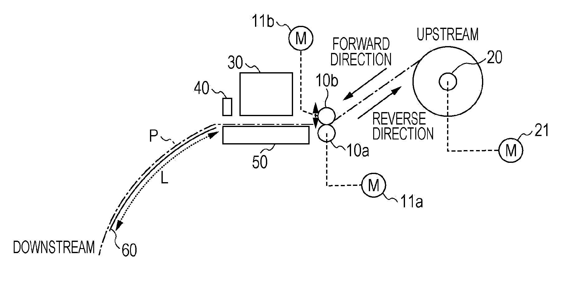
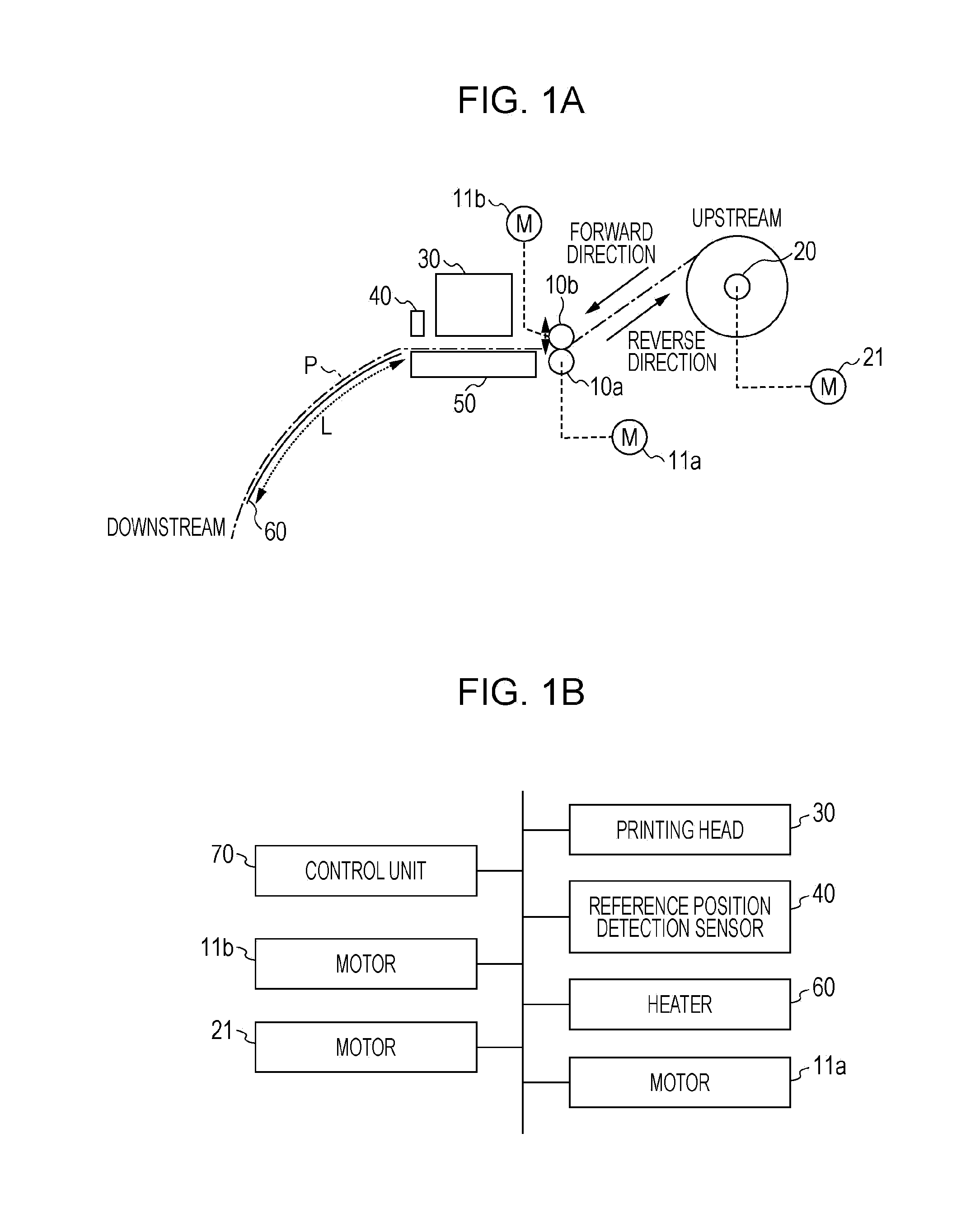
[0026]FIG. 1A is a diagram which schematically shows a configuration of an ink jet printer according to an embodiment of the invention, and FIG. 1B is a diagram which shows a control unit included in the ink jet printer, and hardware which is controlled by the control unit. The ink jet printer according to the embodiment of the invention includes a printing head 30 which ejects ink, transports a printing medium P which is shown by one dot and dashed line in FIG. 1A on a platen 50, specifies a print start position by detecting a reference mark (+ mark or the like) on the printing medium using a reference position detection sensor 40, and performs printing by ejecting ink from the printing head 30.

[0027]In addition, in the embodiment, the printing head 30 is a hea...


PUM


Abstract

A printer is configured which includes, a printing head; a first transport mechanism which transports a printing medium along a transport path; a second transport mechanism which transports the printing medium along the transport path between the printing head and the first transport mechanism; a forward transport control unit which executes a forward transport control transporting the printing medium to the printing head side using the second transport mechanism while applying a load to the printing medium using the roller, and printing a coloring agent to the printing medium using the printing head; and a reverse transport control unit which executes a reverse transport control transporting the printing medium to the first transport mechanism side using the second transport mechanism while applying a load which is smaller than that in the forward transport control to the printing medium using the roller.

Description

BACKGROUND[0001]1. Technical Field[0002]The present invention relates to a printer which transports a printing medium using a roller.[0003]2. Related Art[0004]In the related art, there is provided a technology in which a printing medium is transported in a state where the printing medium is pinched by a plurality of rollers. For example, in JP-A-2004-98698, a paper feeding roller, or a transport roller which transports the printing medium by pinching the printing medium using two rollers is disclosed.[0005]In the related art, in a type of a printer such as an ink jet printer in which it is necessary to fix a coloring agent to a printing medium after printing the coloring agent, such as ink or the like, on the printing medium, it was difficult to perform high speed printing without generating ink transfer. That is, when it has a configuration in which the coloring agent is dried naturally, or by using a heater or the like in order to fix the coloring agent to the printing medium, it ...

Claims


Application Information

Patent Timeline
IPC IPC(8): B41J15/16
CPCB41J15/16B41J11/42
Inventor HAYASHI, TORU
Owner SEIKO EPSON CORP
Features
  • Generate Ideas
  • Intellectual Property
  • Life Sciences
  • Materials
  • Tech Scout
  • Unparalleled Data Quality
  • Higher Quality Content
  • 60% Fewer Hallucinations
Learn More