Image forming apparatus
- Summary
- Abstract
- Description
- Claims
- Application Information
AI Technical Summary
Benefits of technology
Problems solved by technology
Method used
Image

Examples
first embodiment
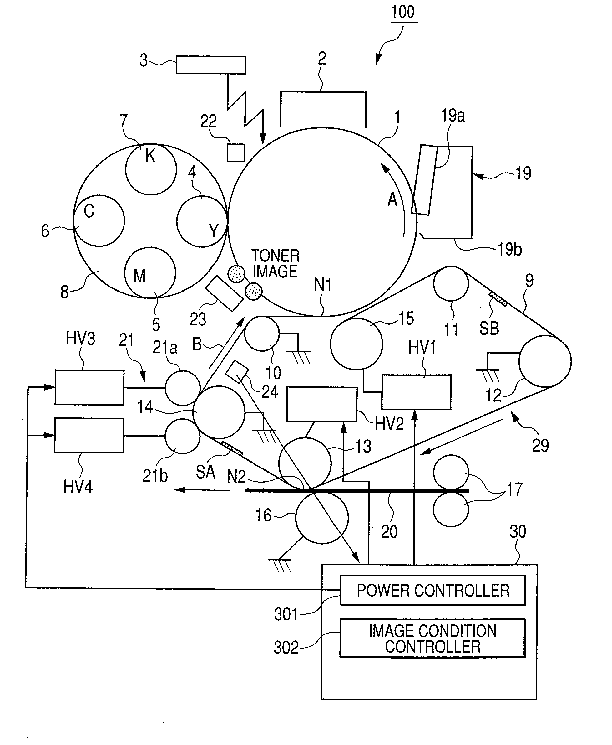
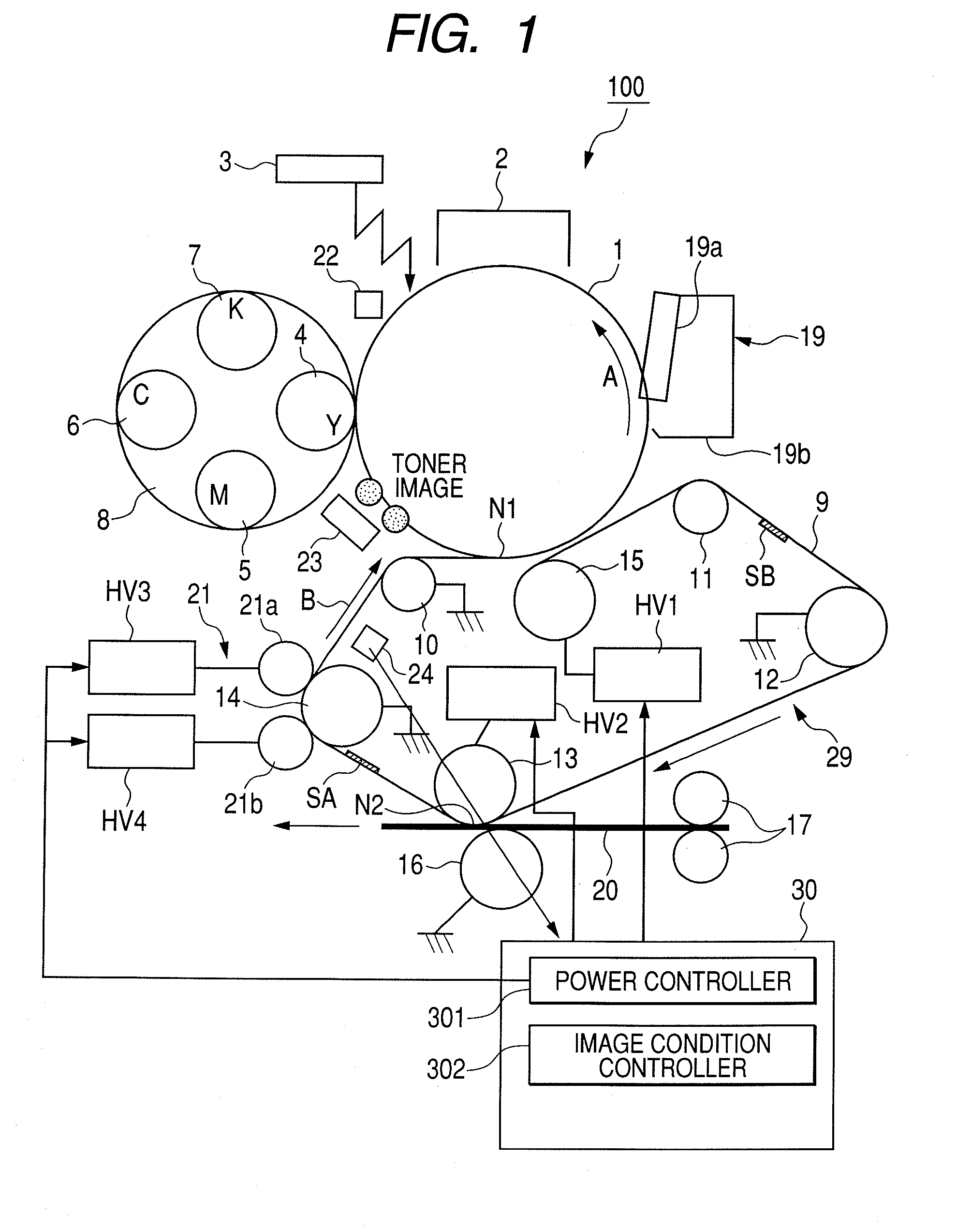
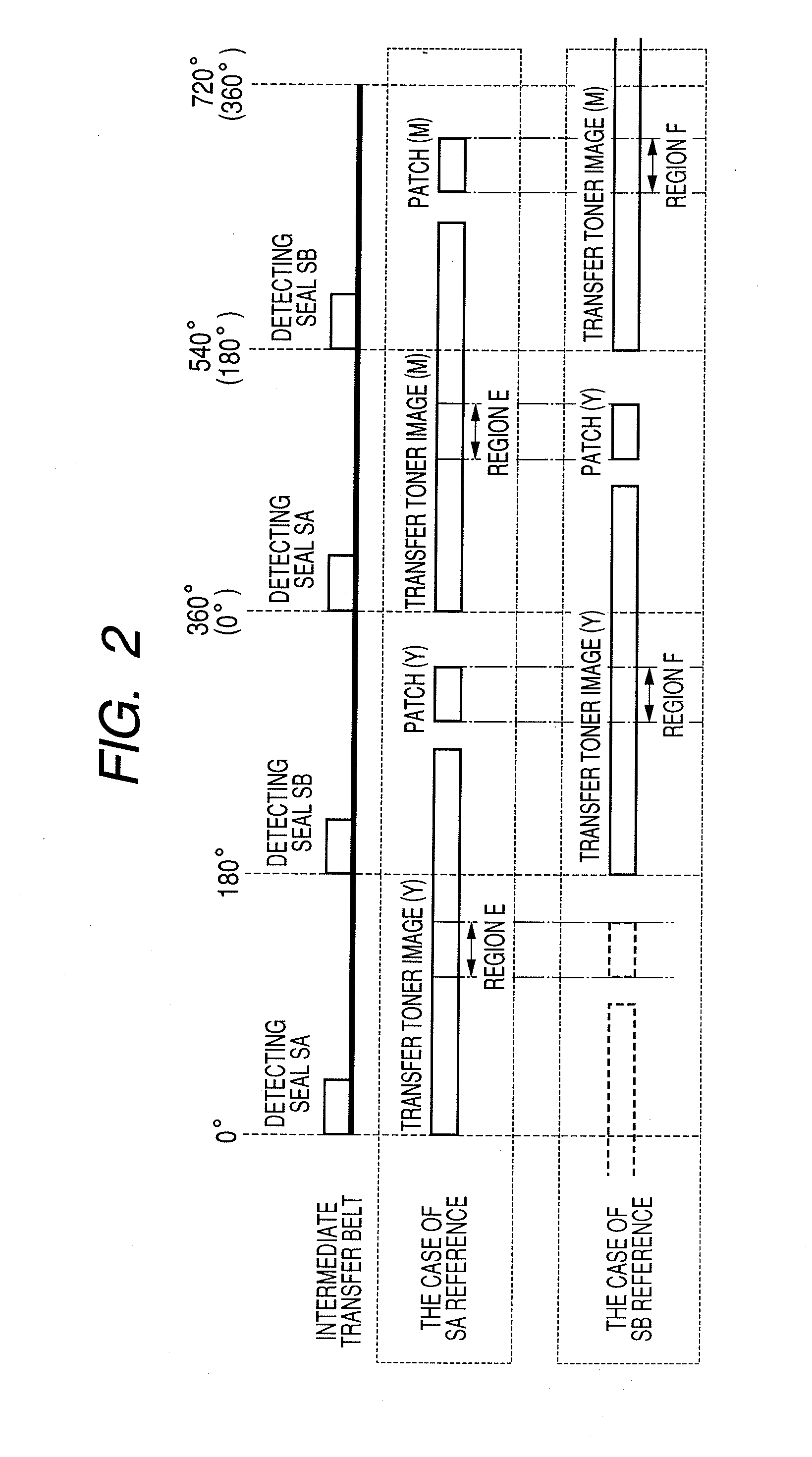
[0061]FIG. 7 is a time chart for control in the first embodiment. In the first embodiment, in the post-rotation of each job, a voltage in no toner image state is applied (that is, a bias voltage is applied in a state where no toner images are formed on the photosensitive drum: hereinbelow, such a state is expressed as “voltage is applied in no toner image state”) only in the region E (or F: FIG. 2) of the intermediate transfer belt 9 by using the primary transfer roller 15, thereby locally increasing the impedance.
[0062]As illustrated in FIG. 1, between the two detecting seals SA and SB adhered to the back surface of the intermediate transfer belt 9, the seal on the front side is called a detecting seal SA and the seal on the rear side is called a detecting seal SB. The main motor is made operative synchronously with the signal to start the image creation. Assuming that the detecting seal detected earlier by the I-Top detecting sensors 24 is, for example, the detecting seal SA, the ...
second embodiment
[0076]FIG. 8 is a time chart for control in the second embodiment. In the second embodiment, an impedance is locally increased by applying a high voltage only to the region E (or F: FIG. 2) of the intermediate transfer belt 9 by using the secondary transfer inner roller 13. In the control of the second embodiment, portions common to those in the first embodiment will be described with reference to FIG. 7.
[0077]It is now assumed that the main motor is made operative synchronously with the image creation start signal and the detecting seal SA on the front side has been detected first by the I-Top detecting sensors 24. As illustrated in FIG. 7, the seal SA is used as a reference of the time base and the transfer toner image and the patch toner image for the concentration detection of yellow (Y) are formed on the photosensitive drum 1. The transfer toner image is primarily transferred onto the intermediate transfer belt 9 by applying the primary transfer bias voltage (+2000V) to the pri...
third embodiment
[0086]FIG. 9 is a flowchart for control in the third embodiment. In the third embodiment, after completion of the execution of the previous impedance variation reducing mode, whenever the number (n) of accumulation output sheets of the image creation reaches the specific number of sheets (M=500), the present impedance variation reducing mode is executed. In the impedance variation reducing mode, by using the primary transfer roller 15, the primary transfer bias voltage is applied in the no toner image state to the interval of the intermediate transfer belt 9 which is in contact with the patch toner image for the concentration detection. Since the creation and the transfer / non-transfer of the transfer toner images and the patch toner images for the concentration detection are similar to those in the first embodiment, they will be described with reference to FIG. 7.
[0087]As illustrated in FIG. 7, it is now assumed that the main motor is made operative synchronously with the signal to ...
PUM
 Abstract
Description
Claims
Application Information
 - Generate Ideas
- Intellectual Property
- Life Sciences
- Materials
- Tech Scout
- Unparalleled Data Quality
- Higher Quality Content
- 60% Fewer Hallucinations
Browse by: Latest US Patents, China's latest patents, Technical Efficacy Thesaurus, Application Domain, Technology Topic, Popular Technical Reports.
© 2025 PatSnap. All rights reserved.Legal|Privacy policy|Modern Slavery Act Transparency Statement|Sitemap|About US| Contact US: help@patsnap.com