Easy Transportable Vortex Type Gas Lamp

a vortex type, gas lamp technology, applied in the direction of combustion types, burners, combustion processes, etc., can solve the problems of not easy and safe to prevent air from entering through the ports to extinguish the flame, and discussed nothing as to how to solve a problem, etc., to facilitate disengagement, increase height, and stable shape

Active Publication Date: 2012-09-13
PRO IRODA INDS
View PDF0 Cites 9 Cited by
  • Summary
  • Abstract
  • Description
  • Claims
  • Application Information

AI Technical Summary

Benefits of technology

[0007]Moreover, the gas lamp includes the carrier mechanism adapted to be grasped. The carrier mechanism facilitates disengagement of the first and second main structures for fuel refill and easy transportation of the second main structure. Moreover, the gas lamp includes external air induced into each passage through the fluid entry zone and exited from the fluid acceleration zone and into the shield. The external air directed and swirled and accelerated by each passage, so the gas lamp can produce a flame that is swirled and has an augmented height and a stable shape. Additionally, the flame is visible through the shield.

Problems solved by technology

It is, however, not easy and safe to preclude air from entering through the ports to extinguish the flame.
Additionally, Chesney discussed nothing as to how to resolve a problem if fuel for the gas lamp is used up.

Method used


Image

  • Easy Transportable Vortex Type Gas Lamp
  • Easy Transportable Vortex Type Gas Lamp
  • Easy Transportable Vortex Type Gas Lamp

Examples


first embodiment

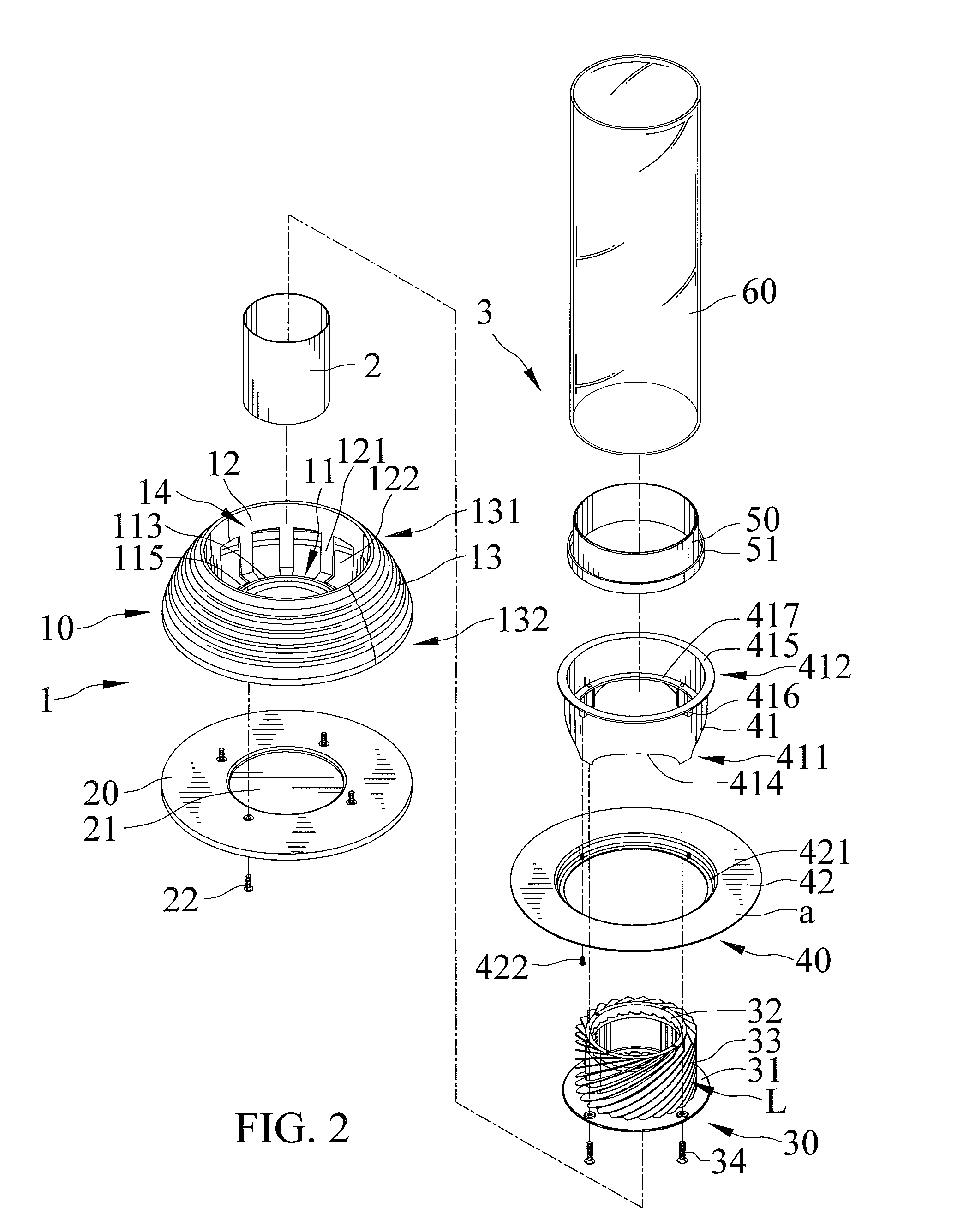
[0031]FIGS. 1 through 7 show an easy transportable vortex type gas lamp in accordance with the present invention. The gas lamp includes first and second main structures 1 and 3.

[0032]The first main structure 1 forms a foundation of the gas lamp. The first main structure 1 includes a reservoir 2 as a fuel tank, a seat 10 and a platform 20. The seat 10 is mounted on the platform 20. The seat 10 and the platform 20 include an air inlet passage b defined therebetween. The air inlet passage b includes the external air flowed thereinto. The seat 10 defines a bottom 11, an inner peripheral wall 12, and an outer peripheral wall 13. The bottom 11 includes a first wall 111 and a second wall 112. The first wall 111 includes an annular circumference. The first wall 111 includes the reservoir 2 received and retained therein. The second wall 112 includes a horizontal surface extending radially outwardly from the first wall 111. The second wall 112 and the inner peripheral wall 12 delimit a chambe...

third embodiment

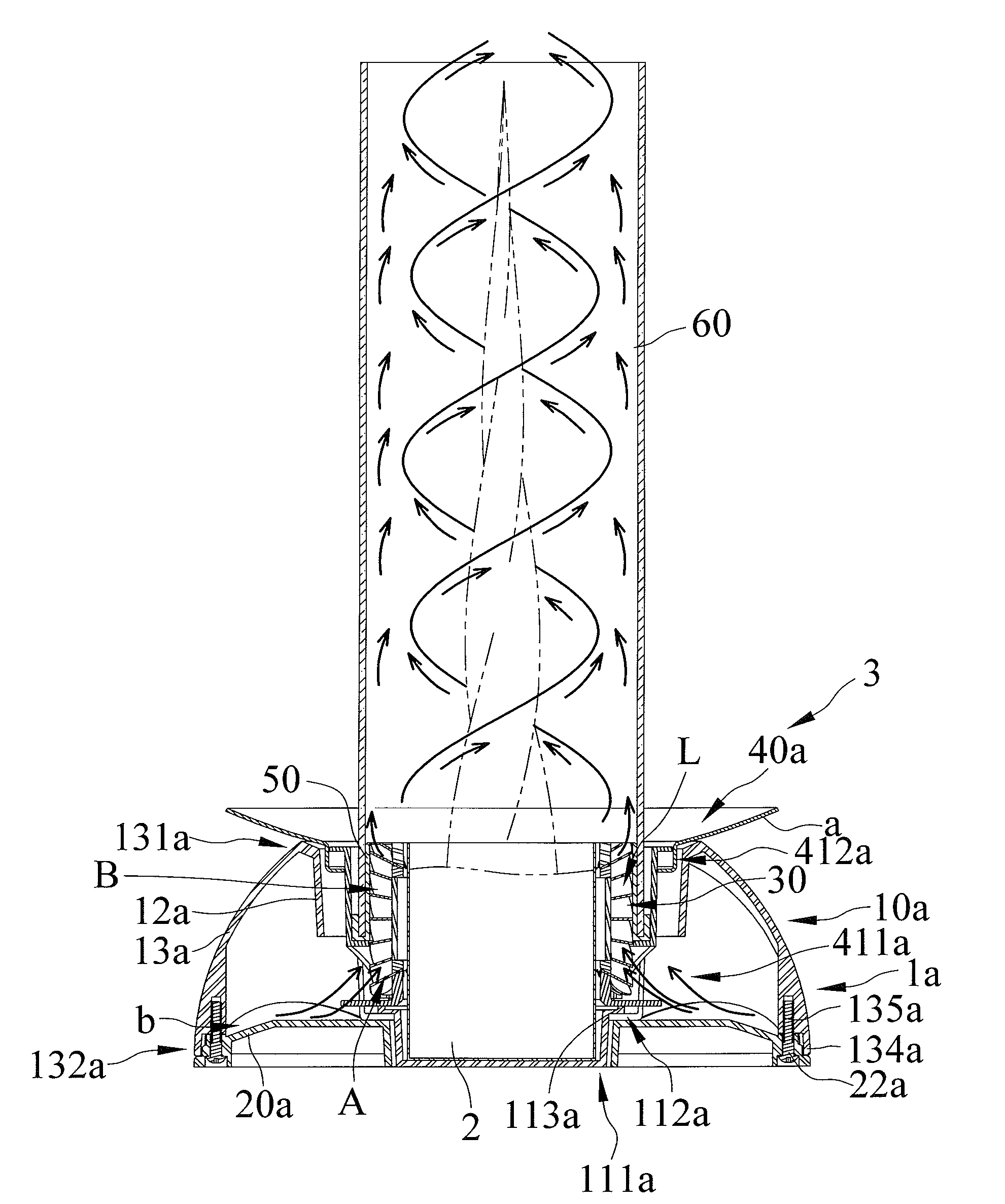
[0040]FIGS. 9 through 14 show an easy transportable vortex type gas lamp in accordance with the present invention. The gas lamp includes first and second main structures 1a and 3. The first main structure la includes a seat 10a and a platform 20a. The seat 10a is mounted on the platform 20a. The seat 10a and the platform 20a include an air inlet passage b defined therebetween. The air inlet passage b includes the external air flowed thereinto. The seat 10a defines a bottom 11a, an inner peripheral wall 12a, and an outer peripheral wall 13a. The bottom 11a includes a first wall 111a and a second wall 112a. The first wall 111a includes an annular circumference. The first wall 111a includes the reservoir 2 received and retained therein. The second wall 112a includes a horizontal surface extending radially outwardly from the first wall 111a. The second wall 112a and the inner peripheral wall 12a delimit a chamber 14a. The chamber 14a includes the second main structure 3 partially and re...

fourth embodiment

[0043]FIGS. 15 through 18 show an easy transportable vortex type gas lamp in accordance with the present invention. The gas lamp includes first and second main structures 1c and 3b. The first main structure 1c includes a seat 10c. The seat 10c defines a bottom 11c, an inner peripheral wall 12c, and an outer peripheral wall 13c and includes the second main structure 3b directly and releasably mounted thereon. The bottom 11c includes a first wall 111c and a second wall 112c. The first wall 111c includes an annular circumference. The first wall 111c includes the reservoir 2 received and retained therein. The second wall 112c includes a horizontal surface extending radially outwardly from the first wall 111c. The second wall 112c and the inner peripheral wall 12c delimit a chamber 14c. The chamber 14c includes the external air flowed thereinto. The chamber 14c also includes the second main structure 3b partially and releasably received therein and is in fluid communication with the flui...


PUM


Abstract

A gas lamp includes first and second main structures. The first main structure forms a foundation of the gas lamp and includes a reservoir as a fuel tank. The second main structure is directly and releasably mounted atop of the first main structure. The second main structure includes a fluid guiding member, a carrier mechanism, a covering member, and a shield. The fluid guiding member defines a fluid entry zone and a fluid acceleration zone. The covering member includes the fluid acceleration zone circumferentially surrounded therein. The gas lamp includes the carrier mechanism adapted to be grasped, which facilitates disengagement of the first and second main structures for fuel refill and easy transportation of the second main structure.

Description

BACKGROUND OF THE INVENTION[0001]1. Field of the Invention[0002]The present invention relates to a vortex type gas lamp and, particularly to, a vortex type gas lamp that is easy transportable.[0003]2. Description of the Related Art[0004]U.S. Pat. No. 7,097,448 to Chesney discloses a vortex type gas lamp for producing an upwardly-directed vortex flame of combustible gas inside a surrounding and confined boundary of rotating body of air. An interface is located between the body of air which is devoid of gas and a central region of gas which is bounded by the interface during the operation of the gas lamp. All of the combustion of gas substantially occurs inside the interface. The gas lamp has a central axis and includes a base supplying combustible gas without air at and nearly adjacent to the central axis. The gas lamp further includes a shield including first and second axially-extending sections structurally attached to the base in a fluid-sealing relationship. The first and second...

Claims


Application Information

Patent Timeline
Patent Type & Authority Applications(United States)
IPC IPC(8): F23C7/00
CPCF23C7/002F23D14/28F23C7/02
Inventor CHEN, WEI-LONGCHEN, JAN-NANYEN, TAMMY
Owner PRO IRODA INDS
Why Eureka
Try Eureka