Wall mounting bracket assembly

a technology for mounting brackets and wall substrates, which is applied in the direction of machine supports, suspension devices, furniture parts, etc., can solve the problem of labor-intensive mounting of boxes to wall substrates, and achieve the effect of strengthening the structur

Inactive Publication Date: 2014-01-23
BRAINWAVE RES CORP
View PDF13 Cites 8 Cited by
  • Summary
  • Abstract
  • Description
  • Claims
  • Application Information

AI Technical Summary

Benefits of technology

[0006]The needs described above are fulfilled, at least in part, by use of a self-supporting apparatus that can be placed in a pre-set opening in an existing wall substrate. A frame is configured with a perimeter edge that corresponds to the thickness of the wall substrate. The edge of the frame thus can be in fitting contact with the substrate opening. Flanges on opposite sides of the frame extend in the planar direction of the wall substrate to be in contact with the inner and outer surfaces of the substrate to maintain the frame in position in the wall and to strengthen the structure. The frame can include appropriate mounting portions for mounting electrical boxes or low voltage device within the wall.

Problems solved by technology

The electrical box or low voltage device must be securely attached to the wall substrate as there is no readily available opportunity to mount the box to a closed wall stud.
Attachment of the box to the wall substrate is labor intensive.

Method used


Image

  • Wall mounting bracket assembly
  • Wall mounting bracket assembly
  • Wall mounting bracket assembly

Examples


Embodiment Construction

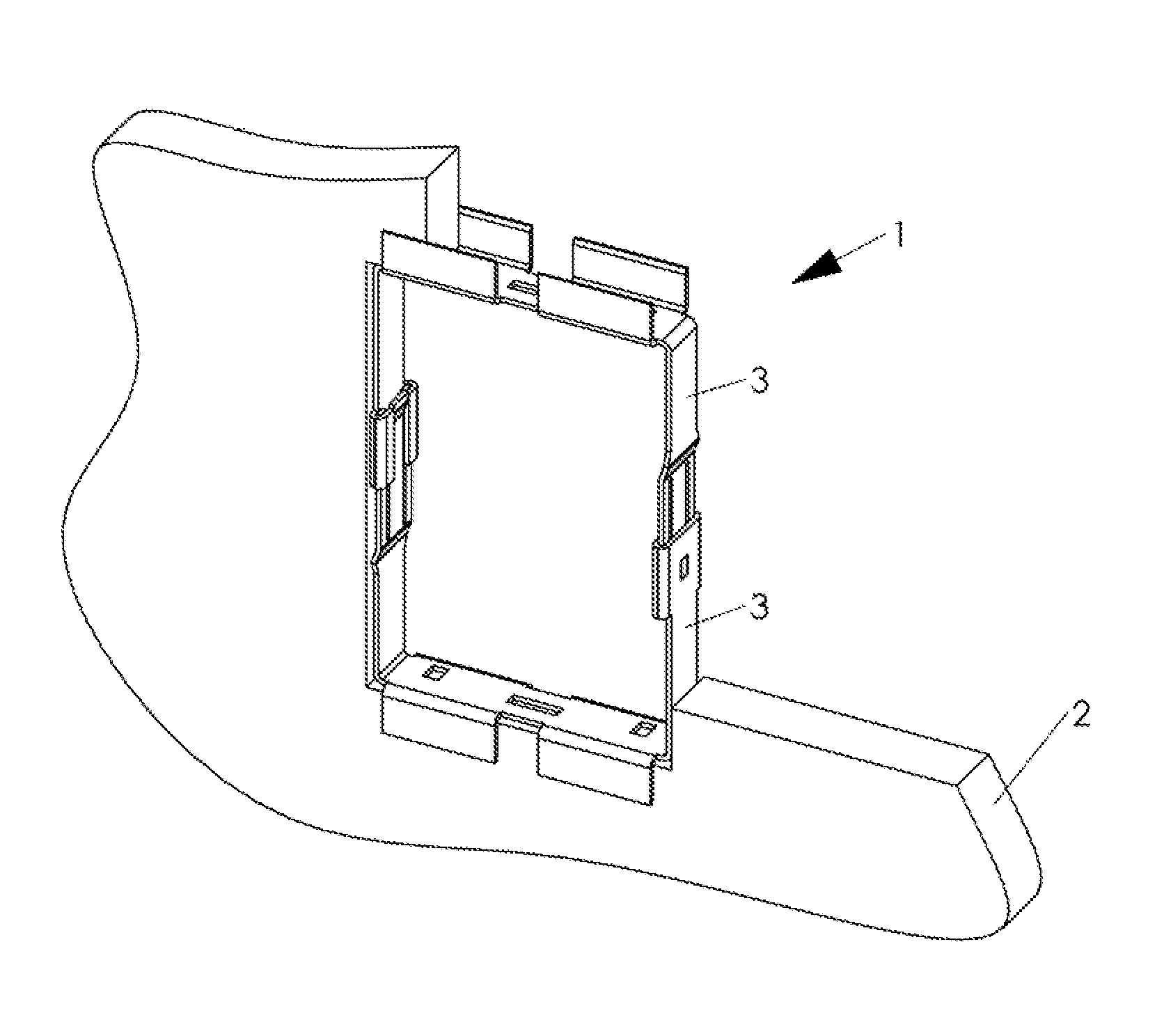
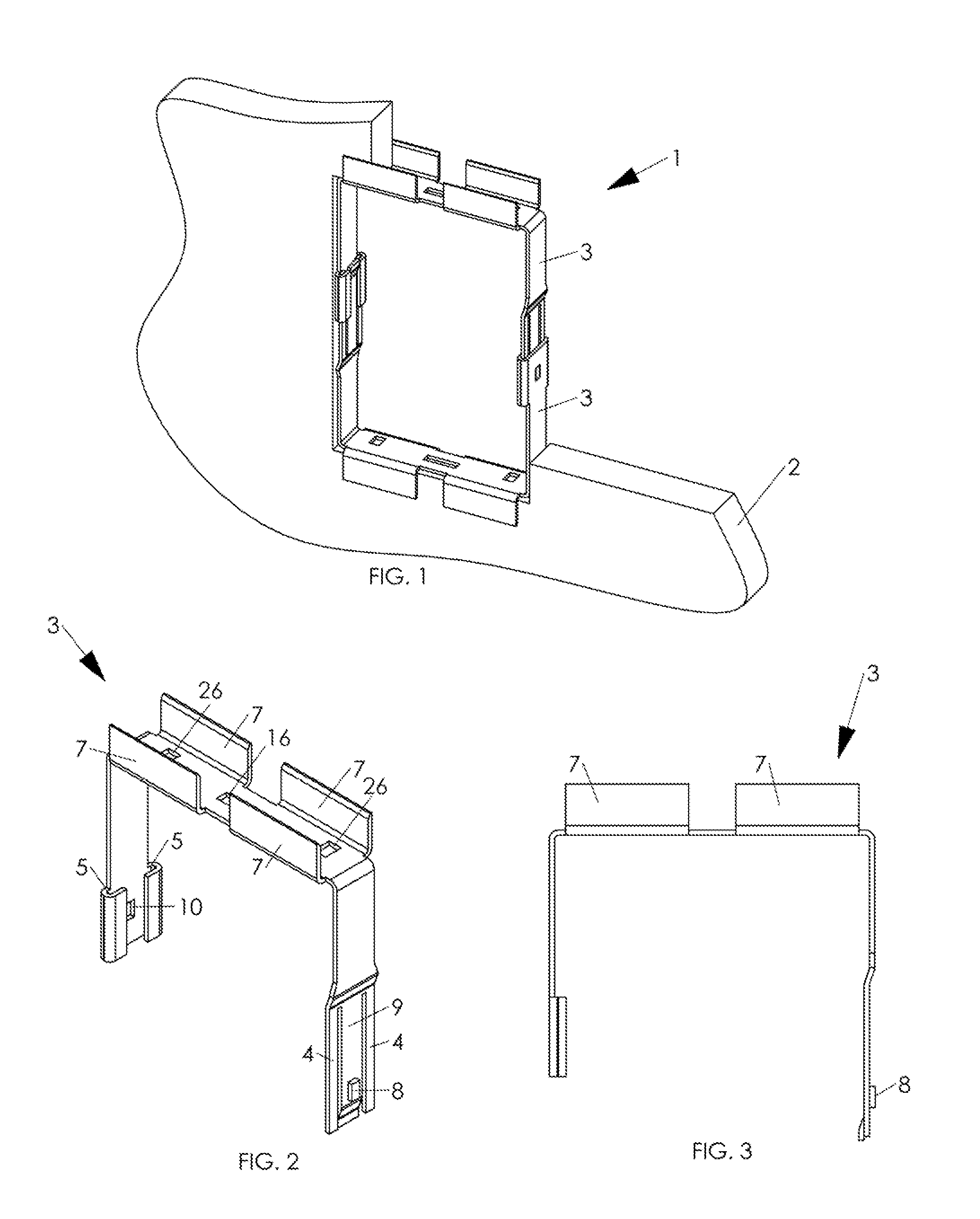
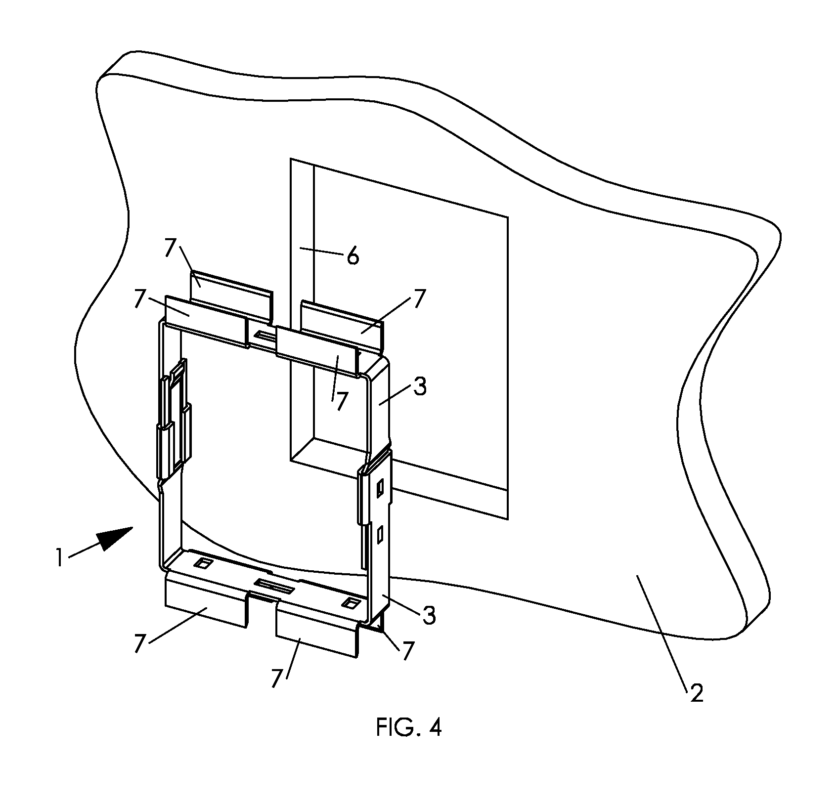
[0137]In FIG. 1, frame assembly 1 is shown mounted in a cut away sheet of drywall 2. The drywall opening can be prepared with a drywall saw. The frame assembly comprises two frame elements 3 that together can be adjusted to define a perimeter that fits the contour of the drywall opening. The depth of the frame corresponds to the depth of the drywall.

[0138]Both frame elements may be identical, as represented more particularly be a frame element perspective view in FIG. 2 and an elevation view in FIG. 3. For clarity of illustration, only the upper frame element 3 of FIG. 1 is shown. Frame element 3, of U-shaped configuration, can be stamped and formed out of metal, for example, galvanized sheet metal . Of course, any other suitable material can be used to form the frame elements. Flanges 7 extend upwardly from the top edges of frame element 3. The frame element sides are of unequal length. The shorter side terminates in a track channel 5. Aperture 10 is formed in the side of the frame...


PUM


Abstract

A bracket assembly includes first and second frame portions movable with respect to each other between a retracted bracket position to an expanded bracket position for contact with opposing portions of a perimeter of an opening in an existing building wall substrate. A flange extends in a planar direction from each frame portion for contact with an outer surface of the wall substrate. A resilient retainer is spaced on the frame from the flange member by a thickness of the wall substrate. The retainer exerts a compressive force on an inner surface of the wall substrate when the bracket assembly is moved to its expanded position.

Description

[0001]This is a continuation-in-part of application Ser. No. 13 / 656,157, filed Oct. 22, 2012, on behalf of inventors Jean-Guy Gagne and James Rodgers, which is a continuation-in-part of application Ser. No. 13 / 101,758, filed May 5, 2011. The benefit of provisional application 61 / 704,232, filed Sep. 21, 2012 on behalf of Jean-Guy Gagne and James Rogers, is claimed under 35 U.S.C. 119(e).BACKGROUND[0002]This disclosure is related to installation of electrical components in building structures, more particularly, to installation of electrical boxes, low voltage devices and the like in existing building walls.[0003]Electrical switches and receptacles require electrical boxes to meet existing electrical codes. In new house or building construction, boxes typically are attached to wall studs or joists before drywall or equivalent sheet material is applied to enclose the wall space. Openings can be cut in the sheet material to accommodate the boxes to be mounted in known positions.[0004]Fo...

Claims


Application Information

Patent Timeline
Patent Type & Authority Applications(United States)
IPC IPC(8): F16M13/02
CPCF16M13/02H02G3/121H02G3/123H02G3/125H02G3/126H02G3/14H04B1/38
Inventor GAGNE, JEAN-GUYROGERS, JAMES W.
Owner BRAINWAVE RES CORP
Why Eureka
Try Eureka