
Apparatuses for improving throwing technique and methods of using same

Inactive Publication Date: 2012-09-13
GEAR
View PDF24 Cites 4 Cited by
  • Summary
  • Abstract
  • Description
  • Claims
  • Application Information

AI Technical Summary

Benefits of technology

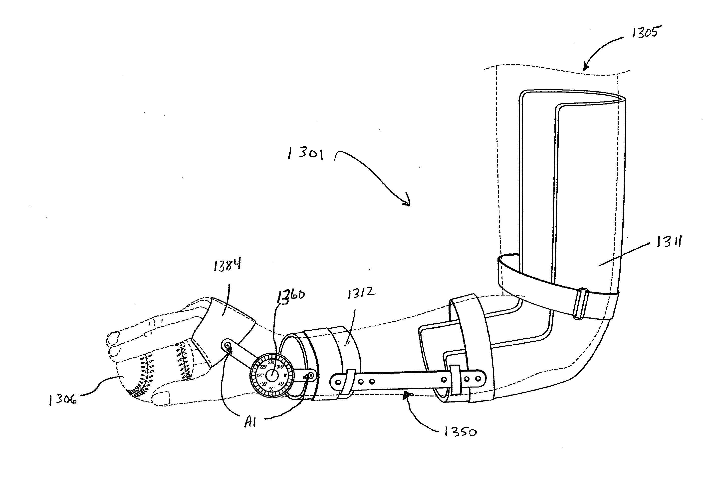
[0009]In accordance with the purposes of various embodiments as described herein, another apparatus for improving throwing technique is provided. The apparatus comprises a first portion configured to at least partially surround at least an upper arm portion of an arm of the user; a second portion comprising a wedge and configured to at least partially surround at least a lower arm and hand portions of the arm of the user; a first flexible portion, the first flexible portion being configured to at least partially surround and secure the upper arm of the user, such that the first flexible portion and the first body portion together substantially encase and immobilize the upper arm of the user; and a second flexible portion, the second flexible portion being configured to at least partially surround and secure the lower arm and hand of the user, such that the second flexible portion and the second body portion together substantially encase and immobilize the lower arm and hand of the user. In these and still other provided embodiments, the wedge of the second body portion may be further configured to create a gap between a palm of the user's hand and the second body portion, the gap further preventing contact between the palm of the user's hand and a ball during use of the apparatus.

Problems solved by technology

In other words, even assuming all other factors equal, an athlete of inferior strength and stamina may, by using a superior technique, outperform an athlete of superior conditioning and stamina who uses an inferior technique.
Adverse effects of improper technique include, but are not limited to poor accuracy, lack of distance, poor rotation or spin on the ball, and a generally heightened risk of injury due to stress placed on the athlete's arm and shoulder muscles.

Method used


Image

  • Apparatuses for improving throwing technique and methods of using same
  • Apparatuses for improving throwing technique and methods of using same
  • Apparatuses for improving throwing technique and methods of using same

Examples


first embodiment 1

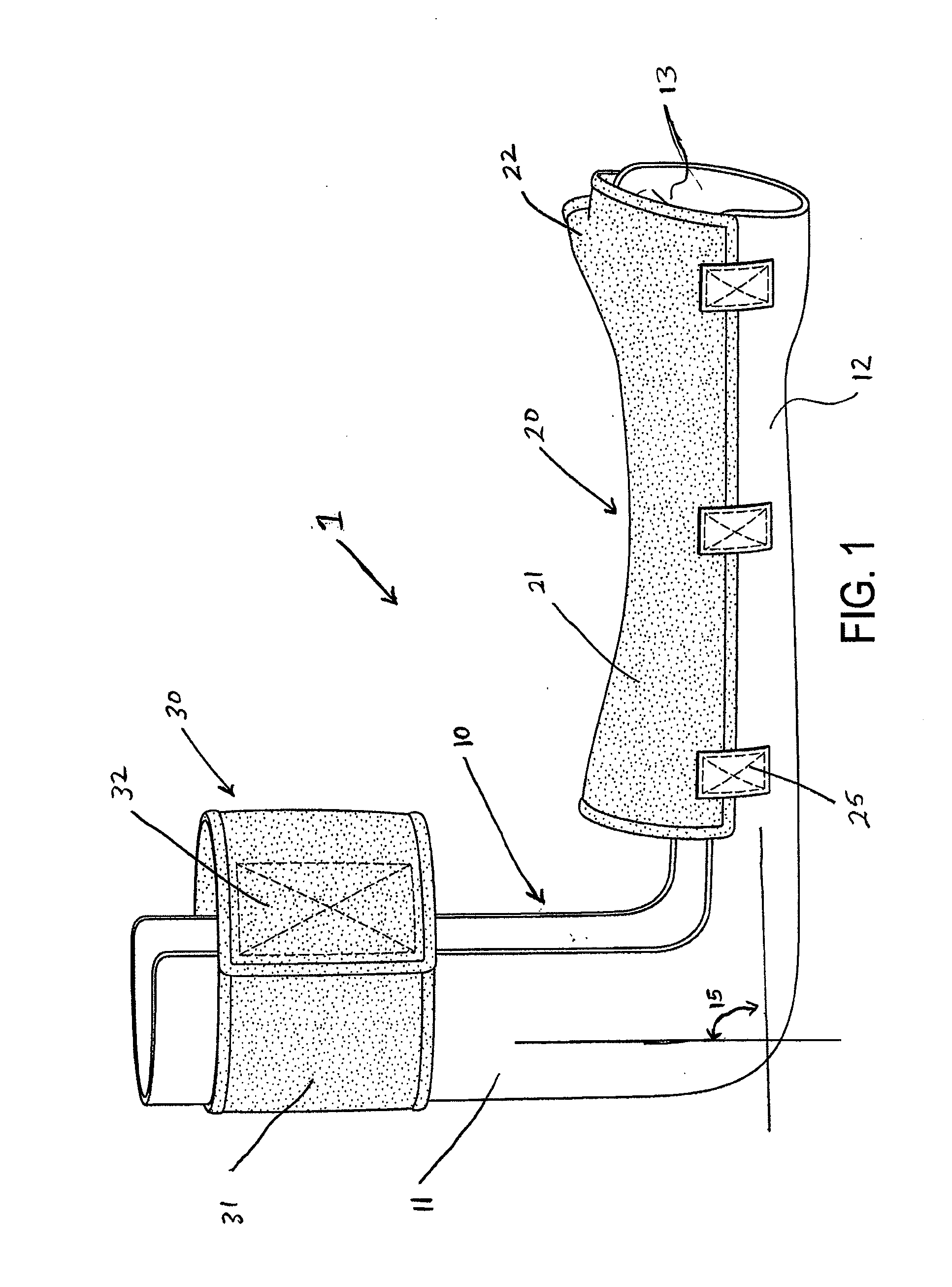
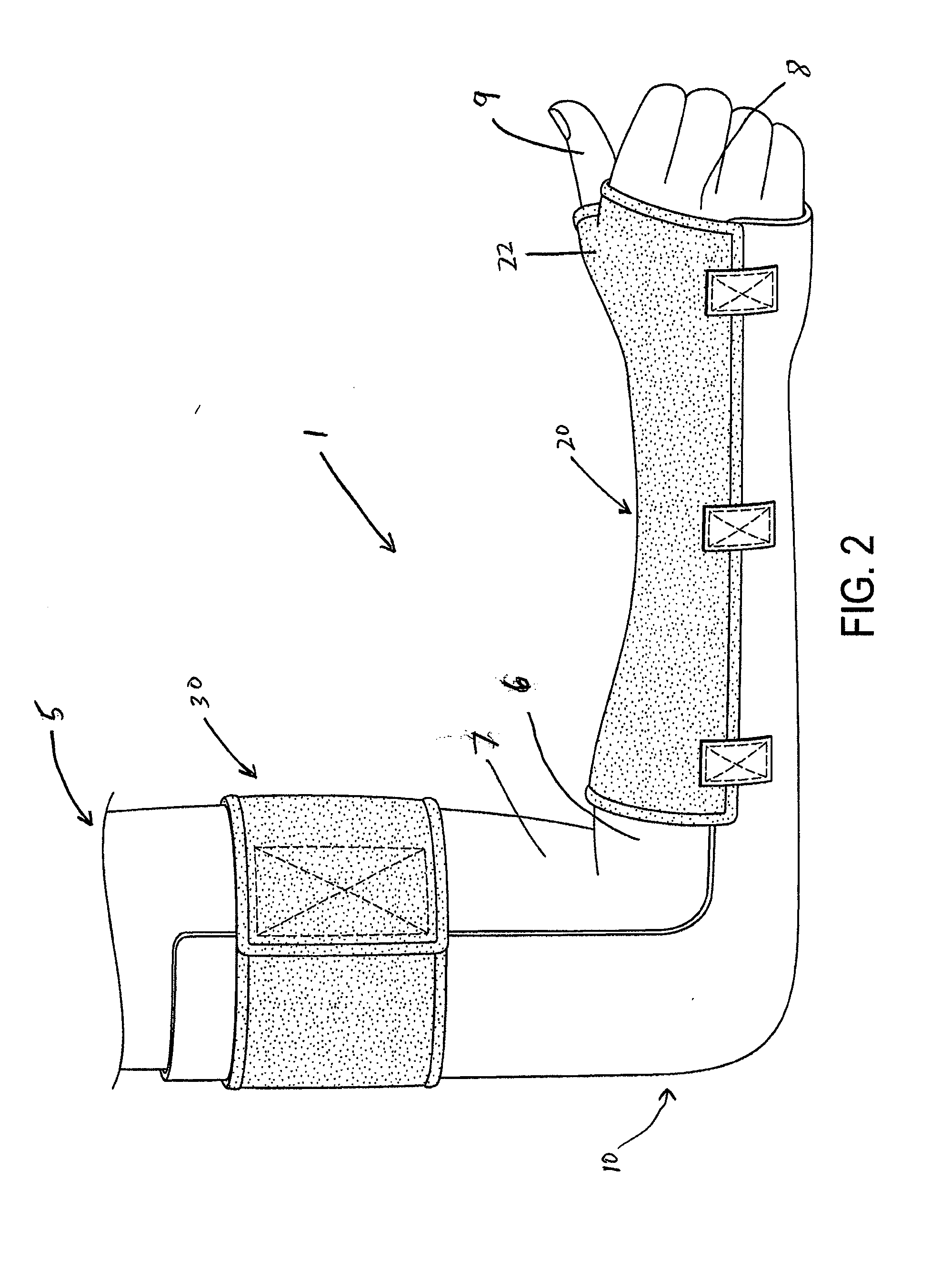
[0049]Reference is now made to FIG. 1, which illustrates a training apparatus 1 comprising a body portion 10, a first flexible portion 20, and a second flexible portion 30. The body portion 10, according to various embodiments, may include a first portion 11, a second portion 12, and a third portion 13. In certain embodiments, the body portion 10 may be constructed from a plastic material such as the non-limiting examples of polycarbonate, polyvinyl chloride (vinyl), polyethylene terephthalate (PET), low or high density polyethylene (LDPE or HDPE), or any combination or alternative of the same, as known or understood in the arts. In other embodiments, the body portion 10, including the first, second and third portions 11, 12, and 13, may be constructed from any of a variety of materials as commonly known or understood in the art as having a desired degree of rigidity sufficient to hold or maintain a user's arm (e.g., 5 in FIG. 2) in place throughout the performance of a throwing mot...


PUM


Abstract

Various embodiments provide apparatuses configured for improving a ball throwing technique of a user thereof. The apparatuses generally comprise one or more body portions configured to at least partially surround at least a first portion of an arm of the user, and one or more flexible portions configured to at least partially surround and secure at least a second portion of the arm of the user, the second portion being oppositely positioned relative to the first portion. The apparatuses may further comprise at least one connector element configured to selectively attach the one or more flexible portions to the one or more body portions. Various embodiments still further incorporate a wedge portion that creates a gap between a user's palm and the ball being thrown. Still other embodiments comprise extension and rotation mechanisms for apparatus adjustments. Methods of using the various apparatuses are also provided.

Description

CROSS-REFERENCE TO RELATED APPLICATION[0001]This application claims priority to U.S. Provisional Patent Application No. 61 / 449,904, filed Mar. 7, 2011, which is incorporated herein by reference, together with any and all attachments and exhibits thereto. The full benefit and priority of this application is claimed.BACKGROUND[0002]1. Field of Invention[0003]The present invention relates generally to apparatuses for improving throwing technique, in particular those comprising at least one body portion and at least one flexible portion configured so as to securely retain at least a portion of a user's arm in a desirable orientation.[0004]2. Description of Related Art[0005]Athletes often employ various training apparatuses and methods to improve the techniques with which they optimize their performance. Oftentimes, these techniques can be as important, if not more important, than any combination of strength, stamina, or talent possessed by a particular athlete. In other words, even assu...

Claims


Application Information

Patent Timeline
IPC IPC(8): A63B69/00
CPCA63B2243/0025A63B63/083A63B2243/0066A63B69/0071A63B2243/007A63B69/0059A63B2209/10A63B2069/0006A63B69/0002A63B69/00
Inventor DROZJOCK, JOHN J.KREIZER-DROZJOCK, DAWN M.
Owner GEAR
Learn More