Measurement device and method for determining a fluid fill level in a fuel tank

a fuel tank and fluid filling technology, applied in the direction of liquid/fluent solid measurement, volume/mass flow by differential pressure, instruments, etc., can solve the problem of small vacuum or overpressure inside the fuel with respect to ambient pressure, and achieve the effect of accurate compensation and easy retrofitting

Active Publication Date: 2012-09-20
AUDI AG
View PDF5 Cites 42 Cited by
  • Summary
  • Abstract
  • Description
  • Claims
  • Application Information

AI Technical Summary

Benefits of technology

[0013]Correcting the signal based on the measured deformation of the fuel tank safely prevents indication of an incorrect fluid level. A vehicle having a fuel tank disposed in the vehicle can advantageously be prevented from becoming stranded because the fuel actually present lasts only for a shorter route than is apparent from the fill level indication.
[0014]According to an advantageous feature of the present invention, the correction device may be designed for measuring an extent of the deformation or a quantity determining the extent of the deformation. This allows a particularly accurate compensation of a misrepresentation of the signal generated by the signal generating unit due to the deformation of the fuel tank.
[0015]The measurement device may include a control device for controlling a display, wherein at least one characteristic curve is stored in the control device, which provides at least one correction value which depends on the extent of the deformation of the fuel tank for correcting the signal of the signal generating unit. The characteristic curve can be used by the control device to correct the signal of the signal generating unit which does not indicate the actual fluid fill level due to the deformation of the fuel tank. When using this type of measurement device, no changes need to be made to the signal generating unit, so that an existing measurement device can be easily retrofitted.
[0017]According to an advantageous feature of the present invention, the at least one pressure sensor may be arranged in the fuel tank and coupled with the control device. The signal generated by the signal generating unit, which does not indicate the actual fluid fill level due to the deformation of the fuel tank and the signal provided by the pressure sensor are processed in the control device. In particular, if a pressure sensor is provided anyway to monitor the pressure in the fuel tank, the signal supplied by the pressure sensor can be easily used for correcting the signal provided by the signal generating unit. To this end, only the specific characteristic curve for the type of the fuel tank needs to be stored in the control device and the control device needs to be designed for processing both signals.
[0025]In this way, it can be ensured that the actually indicated fluid fill level is not falsified by a deformation of the fuel tank. The deformation of the fuel tank can be measured and corrected, in particular, by a correction device.

Problems solved by technology

However, even when a fuel tank is connected with the environment by way of such line provided with the active charcoal filter, a slight vacuum or overpressure with respect to ambient pressure may be generated inside the fuel tank due to temperature changes.

Method used


Image

  • Measurement device and method for determining a fluid fill level in a fuel tank
  • Measurement device and method for determining a fluid fill level in a fuel tank
  • Measurement device and method for determining a fluid fill level in a fuel tank

Examples


Embodiment Construction

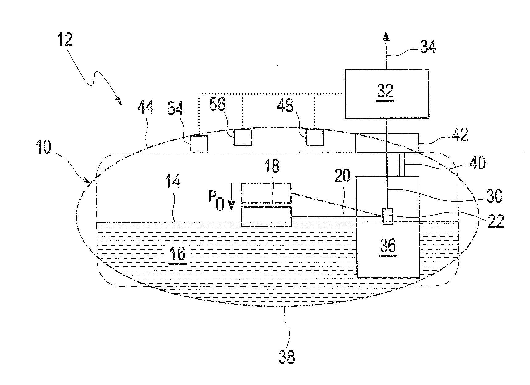
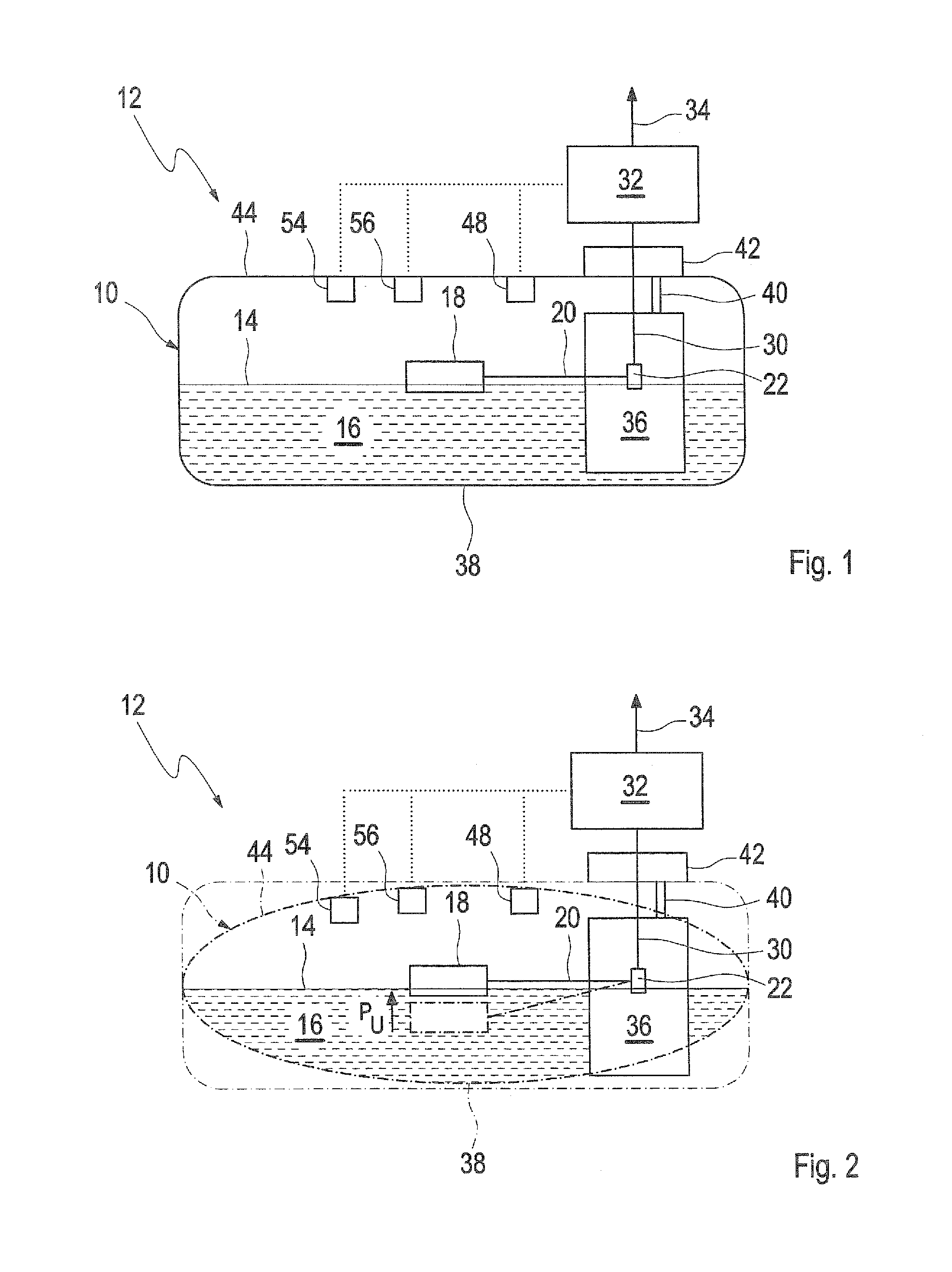
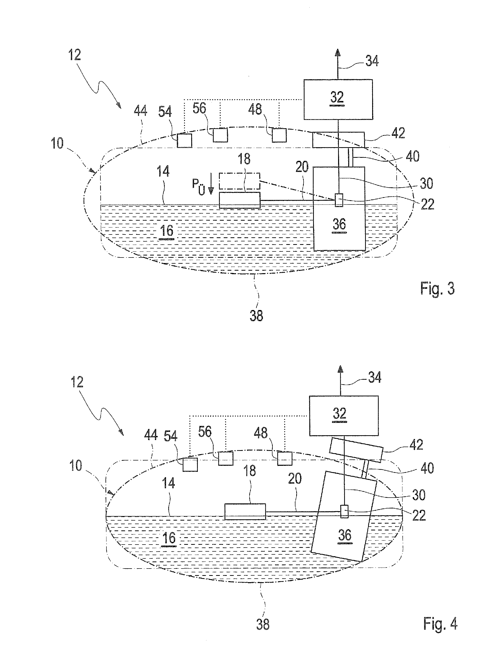
[0033]Throughout all the figures, same or corresponding elements may generally be indicated by same reference numerals. These depicted embodiments are to be understood as illustrative of the invention and not as limiting in any way. It should also be understood that the figures are not necessarily to scale and that the embodiments are sometimes illustrated by graphic symbols, phantom lines, diagrammatic representations and fragmentary views. In certain instances, details which are not necessary for an understanding of the present invention or which render other details difficult to perceive may have been omitted.

[0034]Turning now to the drawing, and in particular to FIG. 1, there is shown in a schematic diagram a fuel tank 10 and a measurement device 12 for determining a fill level 14 of the fuel 16 in the fuel tank 10. The fuel tank 10 is constructed as a pressurized tank of a vehicle, i.e. a closed tank, which is not in communication with the environment of the fuel tank 10 via an...


PUM


Abstract

The invention relates to a measurement device (12) for determining a fluid fill level (14) in a fuel tank (10) for a vehicle. The position of a float (18) in relation to a signal generating unit (22) which can be attached on the fuel tank (10) can hereby be converted into a signal that is correlated with the fill level (14) of the undeformed fuel tank (10). A correction device (48, 54, 56) is designed for measuring a deformation of the fuel tank (10) and is used for correcting the signal. The invention also relates to a method for determining a fluid fill level (14) in a fuel tank (10) for a vehicle.

Description

CROSS-REFERENCES TO RELATED APPLICATIONS[0001]This application claims the priority of German Patent Application, Serial No. 10 2010 045 212.2, filed Sep. 13, 2010, pursuant to 35 U.S.C. 119(a)-(d), the content of which is incorporated herein by reference in its entirety as if fully set forth herein.BACKGROUND OF THE INVENTION[0002]The present invention relates to a measurement device for determining a fluid fill level in a fuel tank for a vehicle. The measurement device includes a float and a signal generating unit which can be fastened on the fuel tank. A position of the float relative to the signal generating unit can be converted to a signal which correlates with the fill level of the undeformed fuel tank. The invention also relates to a method for determining a fluid fill level in a fuel tank.[0003]The following discussion of related art is provided to assist the reader in understanding the advantages of the invention, and is not to be construed as an admission that this related...

Claims


Application Information

Patent Timeline
Patent Type & Authority Applications(United States)
IPC IPC(8): G01F23/30G01F25/00
CPCG01F1/32G01F1/36G01F25/0061G01F22/02G01F23/0076G01F1/363G01F23/804G01F25/20G01F23/36
Inventor HAGEN, HARALD
Owner AUDI AG
Why Eureka
Try Eureka