

Pressure and Measurement by Means of An Optical Fiber
a technology of optical fiber and pressure measurement, applied in the field of optical fiber, can solve the problems of insufficient precision of pressure measurement, insufficient pressure range, inability to accurately measure, etc., and achieve the effect of modest cost and precise pressure measuremen
Inactive Publication Date: 2012-09-20
SCHLUMBERGER TECH CORP
View PDF2 Cites 15 Cited by
- Summary
- Abstract
- Description
- Claims
- Application Information
AI Technical Summary
Benefits of technology
[0023]An implementation of the invention advantageously comprises one or more of the following additional features, which are described in separate paragraphs. These additional features each contribute to achieving precise pressure measurements at modest cost.
[0024]The stress-applying arrangement may comprise a pair of rod-like stress-inducing elements disposed longitudinally and symmetrically with respect to the core.
[0025]The pressure conversion arrangement may comprise a pair of rod-like holes disposed longitu
Problems solved by technology
Indeed, in some applications, the pressure that is in the environment surrounding the fiber optic does not reach the threshold value necessary to be detected by fibers from the a
Method used
View moreImage
Smart ImageViewing Examples

Examples
 PUM
 Abstract
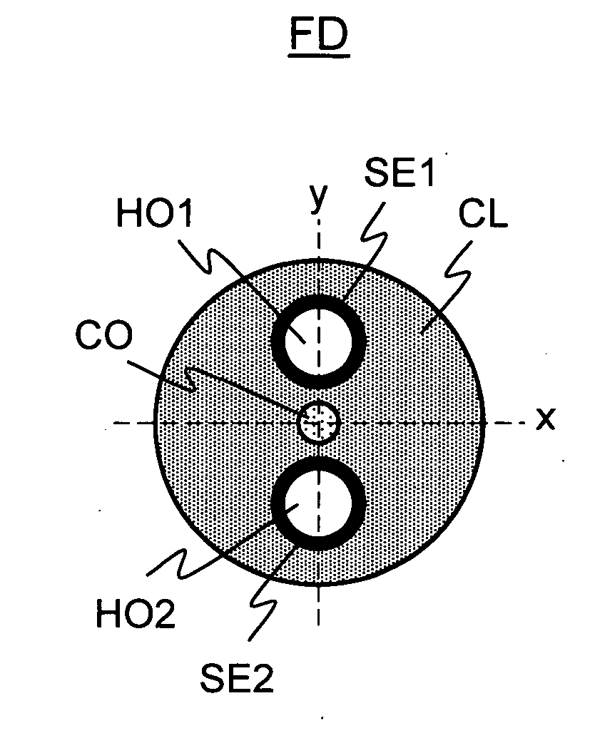
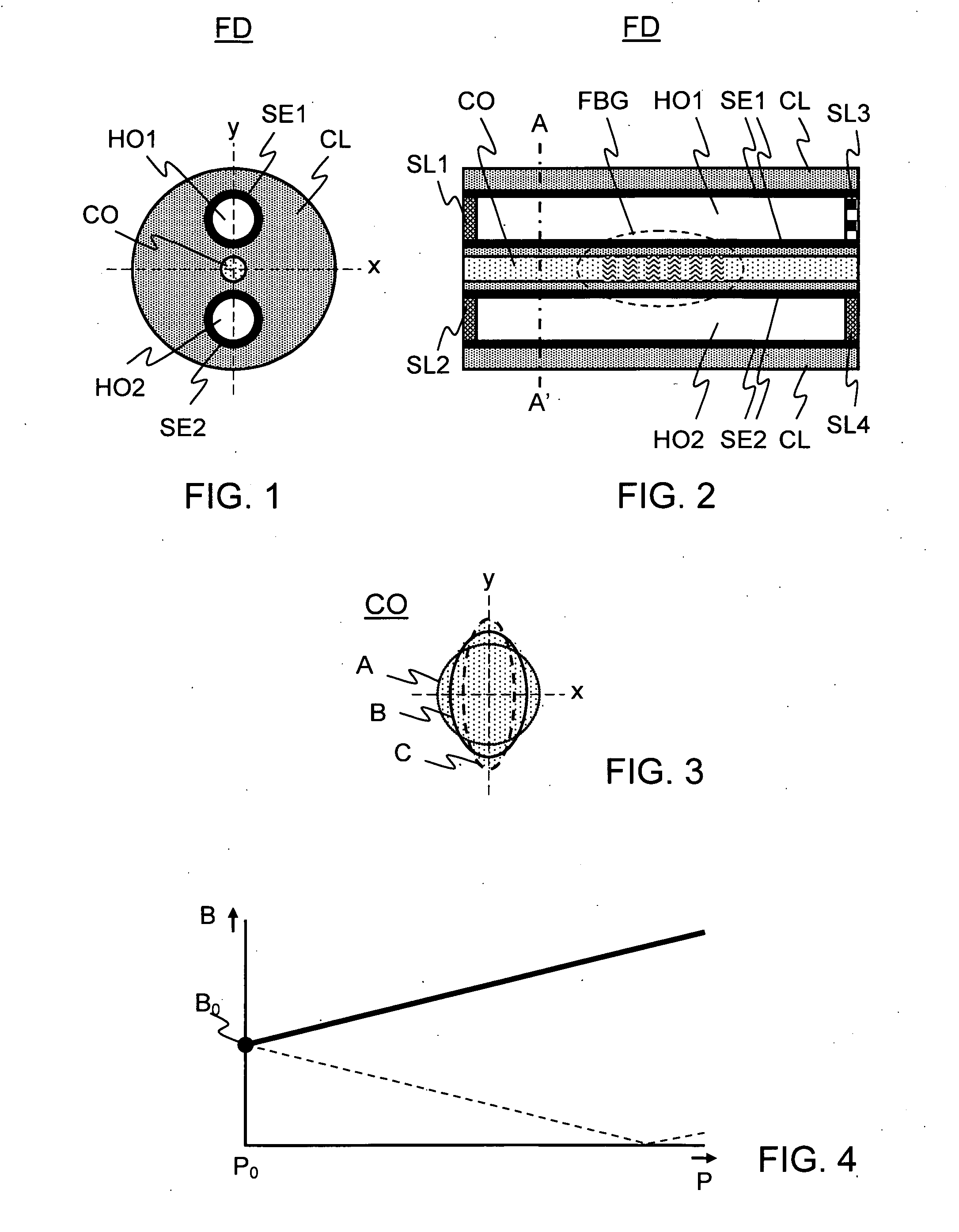
An optical fiber (FD) that can be used for measuring pressure is arranged as follows. The optical fiber (FD) comprises a core (CO) and a cladding (CL) surrounding and contacting the core (CO). A stress-applying arrangement (SE1, SE2), which is embedded in the cladding (CL), applies constant anisotropic stress on the core (CO). This causes the core (CO) to exhibit a deformation. A pressure conversion arrangement (HO1, H02), which is also embedded in the cladding (CL), converts isotropic external pressure applied to the optical fiber (FD) into pressure-dependent anisotropic stress applied to the core (CO). The pressure conversion arrangement (HO1, H02) is disposed with respect to the stress-applying arrangement (SE1, SE2) so that the pressure-dependent anisotropic stress enhances the deformation of the core (CO) caused by the constant anisotropic stress.
Description
FIELD OF THE INVENTION[0001]The present invention generally relates to an optical fiber that can be used for measuring pressure. The optical fiber may be used, for example, to measure pressure in a well that has been drilled for the purpose of oil exploration and production. Other aspects of the invention relate to a pressure measurement system and a method of measuring pressure.BACKGROUND OF THE INVENTION[0002]Optical fiber from the prior art can be arranged as follows for the purpose of measuring pressure. The optical fiber, which has a core, is provided with elements that apply constant anisotropic stress on the core. The core undergoes a deformation so that so that the core exhibits birefringence. Birefringence means that there are two possible modes of light propagation with two different propagation velocities. Hence, the core exhibits two different indices of refraction. In terms of magnitude, the birefringence can be defined as the difference between the two indices of refra...
Claims
Login to View More Application Information
Patent Timeline
 IPC IPC(8): G01L1/24G02B6/34G02B6/02
CPCG01L1/246G02B6/0238G01L11/025
InventorVIGNEAUX, PIERRE
OwnerSCHLUMBERGER TECH CORP