
Air-Tight Push-In and Pull-Out Connector System with Positive Latching

a technology of push-in and pull-out connectors, which is applied in the field of air-tight push-in and pull-out connector systems, can solve the problems of lack of simplicity of push-in/pull-out couplings, or the prior art connector systems are not ideal for air-tight couplings in fail-safe medical applications, so as to prevent accidental disengagement of couplings

Inactive Publication Date: 2013-01-17
SPACELABS HEALTHCARE LLC
View PDF2 Cites 8 Cited by
  • Summary
  • Abstract
  • Description
  • Claims
  • Application Information

AI Technical Summary

Benefits of technology

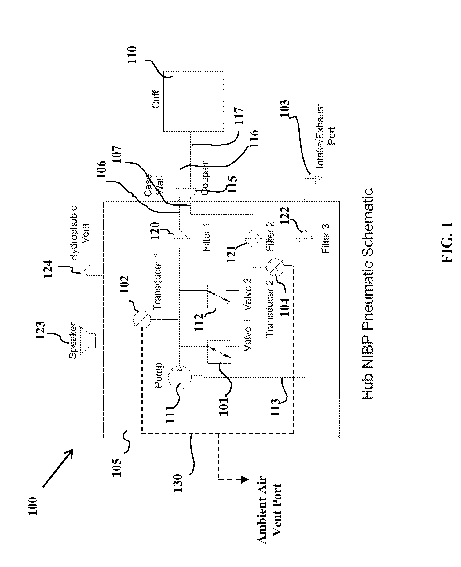
The present invention provides an air-tight push-in / pull-out type of coupling that does not need to be released by pressing or squeezing to allow the connectors to disengage and provide a positive lock with feedback to the user that the connection has been made. This allows for a non-invasive blood pressure determination system to be used with a monitor or hub coupled to a patient cuff using the connector system of the present invention. The connector system includes an adapter with a dual lumen hose slidingly engageable with a hub-end coupler on one side and a patient cuff-end coupler on the other, which allows for one airway to be used to inflate the cuff and the other airway to be used as a sensor air path to enable more accurate measurement of pressure in the cuff. Additionally, the connector system includes a positive latching mechanism to secure the connection between the male adapter and female cuff-end coupler.

Problems solved by technology

The aforementioned prior art connector systems are either not ideal for an air-tight coupling in fail-safe medical applications and / or lack the simplicity of a push-in / pull-out type of coupling that is enhanced by a latch mechanism which does not need to be released by pressing or squeezing to allow the connectors to disengage.

Method used


Image

  • Air-Tight Push-In and Pull-Out Connector System with Positive Latching
  • Air-Tight Push-In and Pull-Out Connector System with Positive Latching
  • Air-Tight Push-In and Pull-Out Connector System with Positive Latching

Examples


Embodiment Construction

[0033]The present invention is directed toward an air-tight push-in and pull-out connector system capable of mating single and multiple lumen hoses comprising at least one positive latch mechanism.

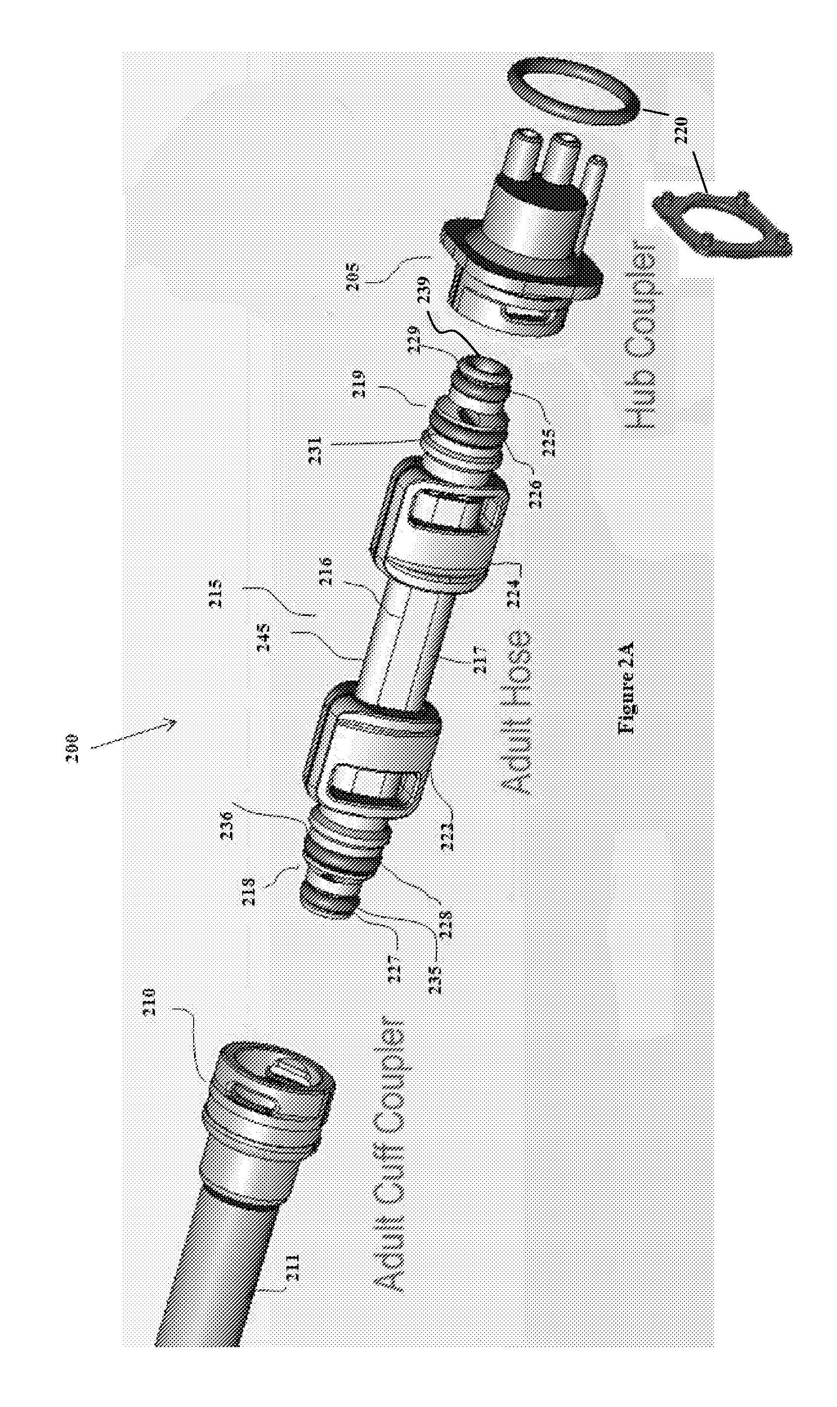
[0034]In one embodiment, the present invention is directed toward an adapter for coupling a blood pressure cuff to a blood pressure manifold, comprising a hose having a first end and a second end, wherein said hose comprises a first lumen and a second lumen wherein said first and second lumens define a first air pathway and a second air pathway respectively; a first end connector integrally formed with said first end wherein said first end connector comprises a first seal and a second seal and wherein each of said first and second seals have different areas; a second end connector integrally formed with said second end wherein said second end connector comprises a third seal and a fourth seal and wherein each of said third and fourth seals have different areas; and wherein a first end of s...


PUM


Abstract

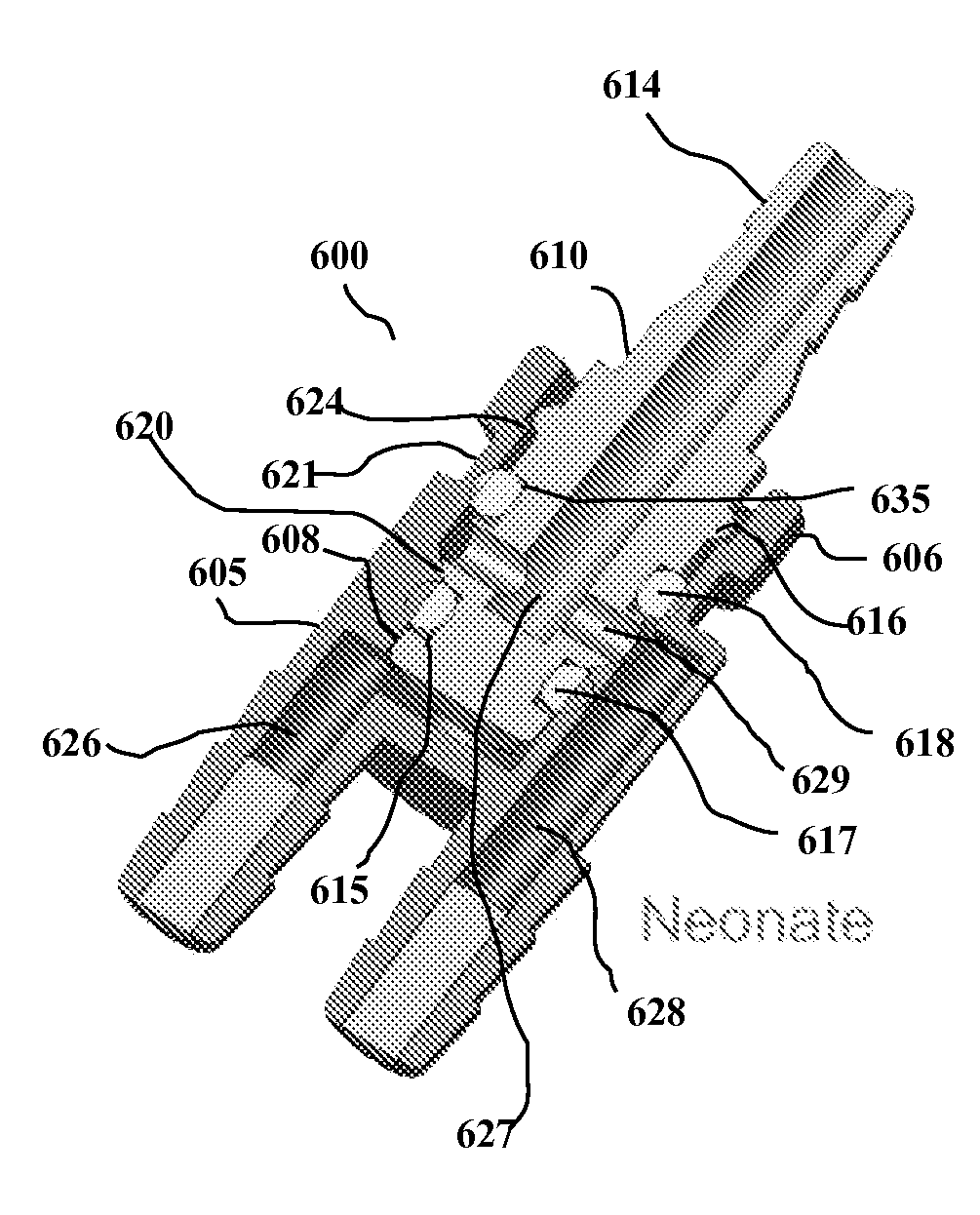
The present specification discloses an adapter for coupling a blood pressure cuff to a blood pressure manifold. In one embodiment, the adapter includes an elastomeric hose having a first end and a second end and a first lumen and a second lumen. The first and second lumens define a first air pathway and a second air pathway respectively. A first end connector is integrally formed with the first end and the second end connector is integrally formed with the second end. The first end connector includes a first seal and a second seal and the second end connector includes a third seal and a fourth seal. The first end of the first lumen terminates proximate to the first seal, the second end of the first lumen terminates proximate to the third seal, the first end of the second lumen terminates proximate to the second seal, and the second end of the second lumen terminates proximate to the fourth seal. The seals are comprised of O-rings, compressible wipers, or any other equally compressible, sealing material. Optionally, for a neonate adapter, the third and fourth seals at the second end connector are replaced by an integrated single lumen tube with a neonate cuff attached at its end.

Description

FIELD OF THE INVENTION[0001]The present invention generally relates to the field of fluid hose connectors or couplings, and more specifically to an air-tight push-in and pull-out connector system capable of mating single and multiple lumen hoses comprising at least one positive latch mechanism.BACKGROUND OF THE INVENTION[0002]Conventional fluid hose connecters include tube couplings comprising a male body and a female body which provide for a positive locking capability when joining the male and female bodies together. For example, U.S. Pat. No. 5,984,378 to Ostrander et al describes “[a] quick connector releasibly connects first and second conduits fixedly mounted in first and second, interconnectable connector bodies. The first body has an axially extending tubular first end, a frusto-conical portion, a reduced diameter shaft and an enlarged second end. A pair of angularly inwardly extending latch arms project from the second body to releasibly engage a peripheral edge on the frus...

Claims


Application Information

Patent Timeline
IPC IPC(8): F16L39/02A61B5/022
CPCA61B5/02141
Inventor GILHAM, JEFFREY JAYWEKELL, WILLIAM OREN
Owner SPACELABS HEALTHCARE LLC
Learn More