Pressure sensor and method for detecting an effective pressure

a pressure sensor and effective pressure technology, applied in fluid pressure measurement, instruments, catheters, etc., can solve the problems of significant measurement error, significant measurement error, and effect accompanying the additional membrane bending, so as to reduce assembly cost and respective measurement inaccuracies, reduce production and installation costs of pressure sensor setup in that way, and efficient compensate

Active Publication Date: 2005-01-06
INFINEON TECH AG
View PDF2 Cites 8 Cited by
  • Summary
  • Abstract
  • Description
  • Claims
  • Application Information

AI Technical Summary

Benefits of technology

It is an advantage of the present invention that due to two pressure detection means, which are disposed in a pressure sensor, an exact pressure measurement is possible independent of an installation position of the pressure sensor. Particularly during acceleration, its measurement value distorting effect can be efficiently compensated.
It is another advantage of the present invention that the pressure sensor can be integrated, since both the first and the second pressure detection means can be integrated on a chip. For that reason, the production and installation costs of a pressure sensor setup in that way are also low.
It is another advantage of the present invention, that the first and the second pressure detection means of the pressure sensor can be calibrated already beforehand to determine the interference dependencies of the respective pressure detection means. Thereby, the inventive pressure sensors can be calibrated already during a production process, wherein further an expensive and inaccurate sensor calibration during installation is omitted. This is particularly advantageous for later installed sensor systems, where pressure sensors are installed in already finished produced wheels, which is always connected with installation inaccuracies. According to the invention, a later calibration with later installed pressure sensors is omitted, whereby further both the assembly cost and respective measurement inaccuracies are reduced.
It is another advantage of the present invention the inventive evaluation means can also be integrated on the chip when the pressure sensor is integrated. Thereby, the requirement of installing a central unit for evaluating the respective pressure measurement signal is avoided, whereby the pressure sensor cost as well as an assembly effort can be reduced.
A further advantage of the present invention can be seen in the fact that for pressure measurement of moving objects silicon pressure sensors in surface micromechanic can be used according to the invention, since, as has already been mentioned, the possibly strong bending of the membrane due to the protective layer during acceleration can be compensated, since the possible interference dependence of the respective pressure detection means can already be determined a priory. Thus, according to the invention, a new field of application is opened up for such pressure sensors.
Another advantage of the present invention lies in the fact that already existing sensor elements can be used for producing the inventive sensor. By a possible on-chip compensation of the acceleration effects, further, the inventive pressure sensors can be used independent of the system and thus in a flexible way.

Problems solved by technology

These accelerations can lead to a significant measurement error in tire pressure sensors, which are also moved in the respective tire.
Due to the own weight of a membrane, an acceleration acting vertically to the membrane also leads to a bending.
Particularly in surface mechanical silicon pressure sensors, which require a protective layer, such as a gel, for media separation, the effect accompanying the additional membrane bending is increased by the protective layer (media protection) deposited on the membrane, such that a significant measurement error occurs when using such sensors.
Due to the acceleration acting vertically to the membrane, however, there is also a measurement error in sensors that require no protective layer.
In that case, a respectively different force, which also leads to a measurement error, acts vertically on the respective membrane during acceleration.
This approach, however, is expensive and difficult to be realized with a later installation of the tire sensors.

Method used


Image

  • Pressure sensor and method for detecting an effective pressure
  • Pressure sensor and method for detecting an effective pressure
  • Pressure sensor and method for detecting an effective pressure

Examples


first embodiment

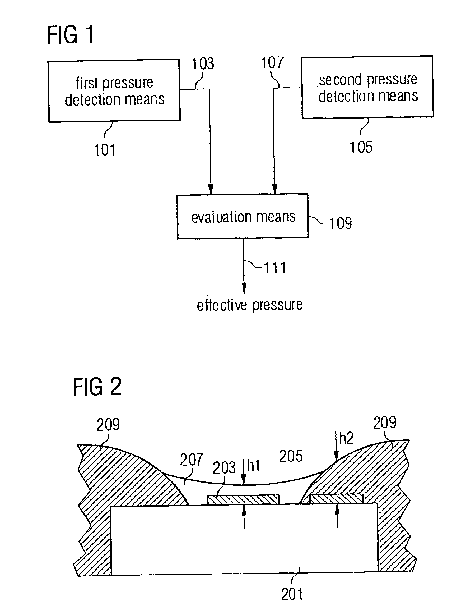
the inventive pressure sensor is illustrated in FIG. 1. The pressure sensor comprises a first pressure detection means 101, which provides a first pressure measurement signal 103. Further, the pressure sensor has a second pressure detection means 105, which provides a second pressure measurement signal 107. Both the first pressure measurement signal 103 and the second pressure measurement signal 107 are received by an evaluation means 109. The evaluation means provides an output signal 111, which characterizes the effective pressure.

The first pressure detection means 101 is formed to measure the effective pressure. This can be realized, for example, by the fact that the first pressure detection means 101 has a first membrane, which provides the first pressure measurement signal 103 based on a deformation (such as bending) during effective pressure. Analogously, the second pressure detection means 105 is formed to detect the effective pressure, for example, with the help of a second...


PUM

PropertyMeasurementUnit
pressureaaaaaaaaaa
pressure detectionaaaaaaaaaa
densityaaaaaaaaaa

Abstract

A pressure sensor for detecting an effective pressure comprises a first pressure detection means for providing a first pressure measurement signal and a second pressure detection means for providing a second pressure measurement signal, wherein the first pressure measurement signal differs from the second pressure measurement signal, as well as an evaluation means for determining the effective pressure based on the first and the second pressure measurement signal. Thereby it is achieved that in a pressure measurement the measurement errors are reduced.

Description

PRIORITY This application claims priority to German application no. 103 29 665.4 filed Jul. 1, 2003. TECHNICAL FIELD OF THE INVENTION The present invention relates to a pressure sensor as well as a method for detecting an effective pressure, which can be used for detecting a tire pressure. BACKGROUND OF THE INVENTION For measuring pressure in a tire of an automobile, pressure sensors are used, which are installed in car tires. When an automobile is moving, centrifugal accelerations of up to 2,000 g occur in car tires. These accelerations can lead to a significant measurement error in tire pressure sensors, which are also moved in the respective tire. Normally, the pressure sensor consists of a flexible membrane, which bends under the influence of an external pressure. This bending (deformation) is measured electronically and is a measure for the external pressure. Due to the own weight of a membrane, an acceleration acting vertically to the membrane also leads to a bending. Par...

Claims


Application Information

Patent Timeline
Patent Type & Authority Applications(United States)
IPC IPC(8): B60C23/04G01L19/02
CPCB60C23/0408G01L15/00G01L19/02
Inventor KANDLER, MICHAEL
Owner INFINEON TECH AG
Why Eureka
Try Eureka