Pivot-Fit Connection Apparatus and System for Photovoltaic Arrays

a technology of photovoltaic arrays and connection devices, applied in the direction of pv power plants, heat collector mounting/support, lighting and heating equipment, etc., to achieve the effect of quick and easy assembly of pv modules

Active Publication Date: 2012-09-20
TESLA INC
View PDF6 Cites 114 Cited by
  • Summary
  • Abstract
  • Description
  • Claims
  • Application Information

AI Technical Summary

Problems solved by technology

Most PV module coupling systems require the time-consuming use of multiple small fasteners.
High part count and slow installation time is a major barrier to reducing PV system costs and adoption.
First, neither of these methods can adequately account for variations in the dimensions of PV modules and couplings due to manufacturing tolerances. PV modules typically vary by approximately ±0.10″ along the length and / or width dimension. When multiple modules are formed into columns in the north-south direction of the PV array, it is critical that any dimensional variations from one module in the column not carry forward to the next module in the column, as the dimensional variations will add up over the length of the column and result in significant dimensional differences from one column to the next. Likewise, the same problem exists with east-west rows of PV modules. This problem, frequently referred to as tolerance take-up, is solved in rail-based systems by spacing the modules in a column more or less from each other on top of mounting rails so that the next module in the column is properly positioned and / or by only linking modules to the rails along one axis, either east-west or north-south. However, in rail-free systems, a PV module is structurally connected to the next module in both the north-south direction and the east-west direction. Thus, if the seams between adjacent east-west modules do not line up because of compounded north-south dimensional variations, then it may be impossible to complete the installation of an array. In other systems compounded east-west variations may cause problems along the north-south axis. Press-fit and hook-type connections do not adequately address or solve the problem of tolerance variations.
Second, press-fit and hook-type connections do not provide a reliable electrical ground bond between adjacent PV modules. Hook-type connections are inherently loose-fitting and thus incapable of providing a consistent, low-resistance ground bond that will withstand weather conditions over time. Similarly, a press-fit connection does not provide a reliable ground bond unless the materials are deformed enough in the connection. In practice, too much force is required to achieve such deformation with standard PV module frame materials such as aluminum, thereby eliminating any time and cost savings that might have occurred since a heavy-duty tool would be required to deliver the force needed for the deformation.
Third, press-fit and hook-type systems cannot reliably provide a strong, durable connection between mating male and female parts. In order to facilitate a quick and easy connection, the female receiving portion in the connection is made wider than the male connecting portion. This results in a loose or unstable connection, which is vulnerable to loosening over time as the PV modules experience mechanical stress due to wind and snow loads.
The reason is that production of tight tolerance PV modules and couplings is very expensive.
In order to accelerate the adoption of solar power, it is necessary to reduce the cost of solar arrays, thus increased costs for tight tolerance parts is not a viable option in the market.
Other limitations of the related art will become apparent to those of skill in the art upon a reading of the specification and a study of the figures.

Method used


Image

  • Pivot-Fit Connection Apparatus and System for Photovoltaic Arrays
  • Pivot-Fit Connection Apparatus and System for Photovoltaic Arrays
  • Pivot-Fit Connection Apparatus and System for Photovoltaic Arrays

Examples


Embodiment Construction

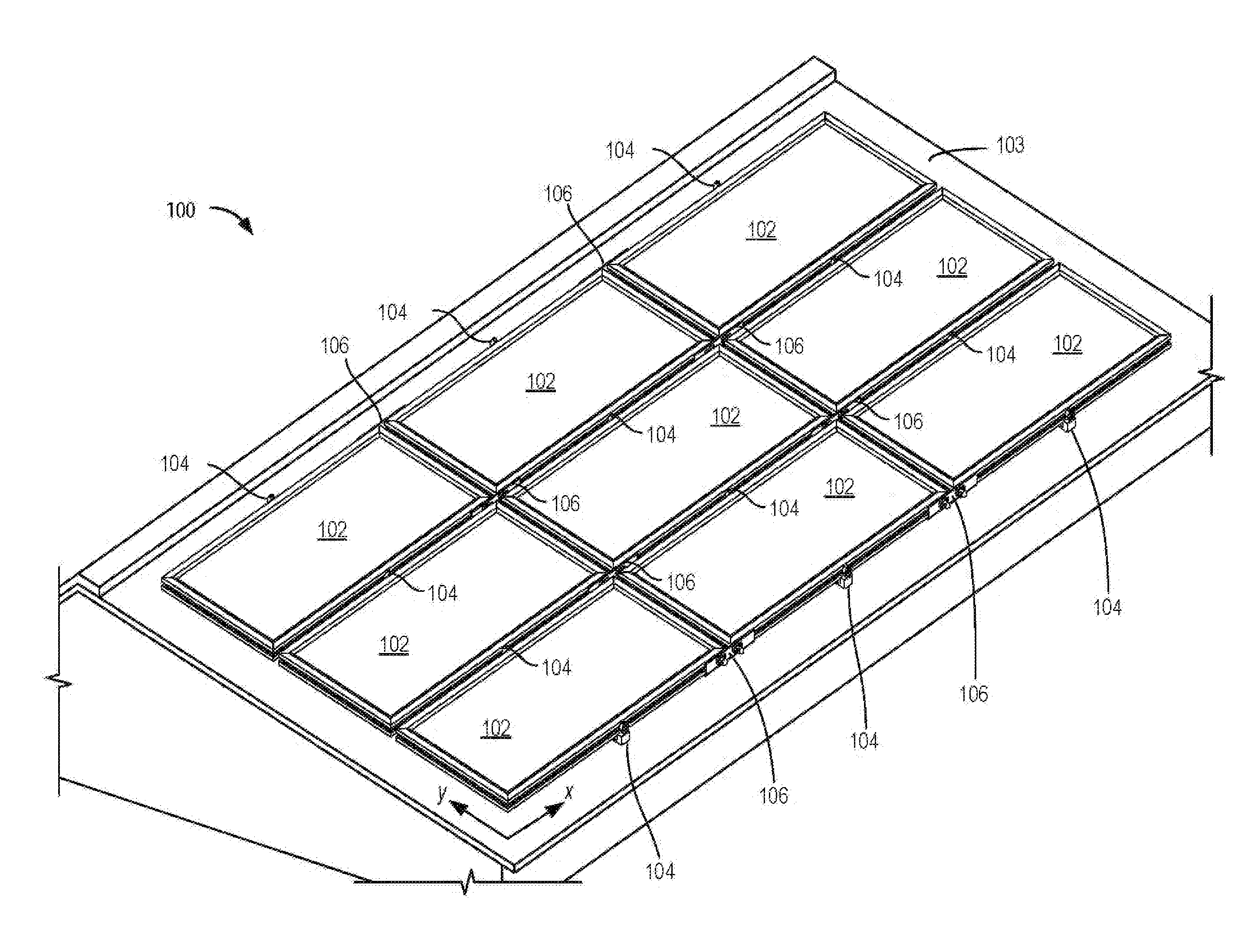
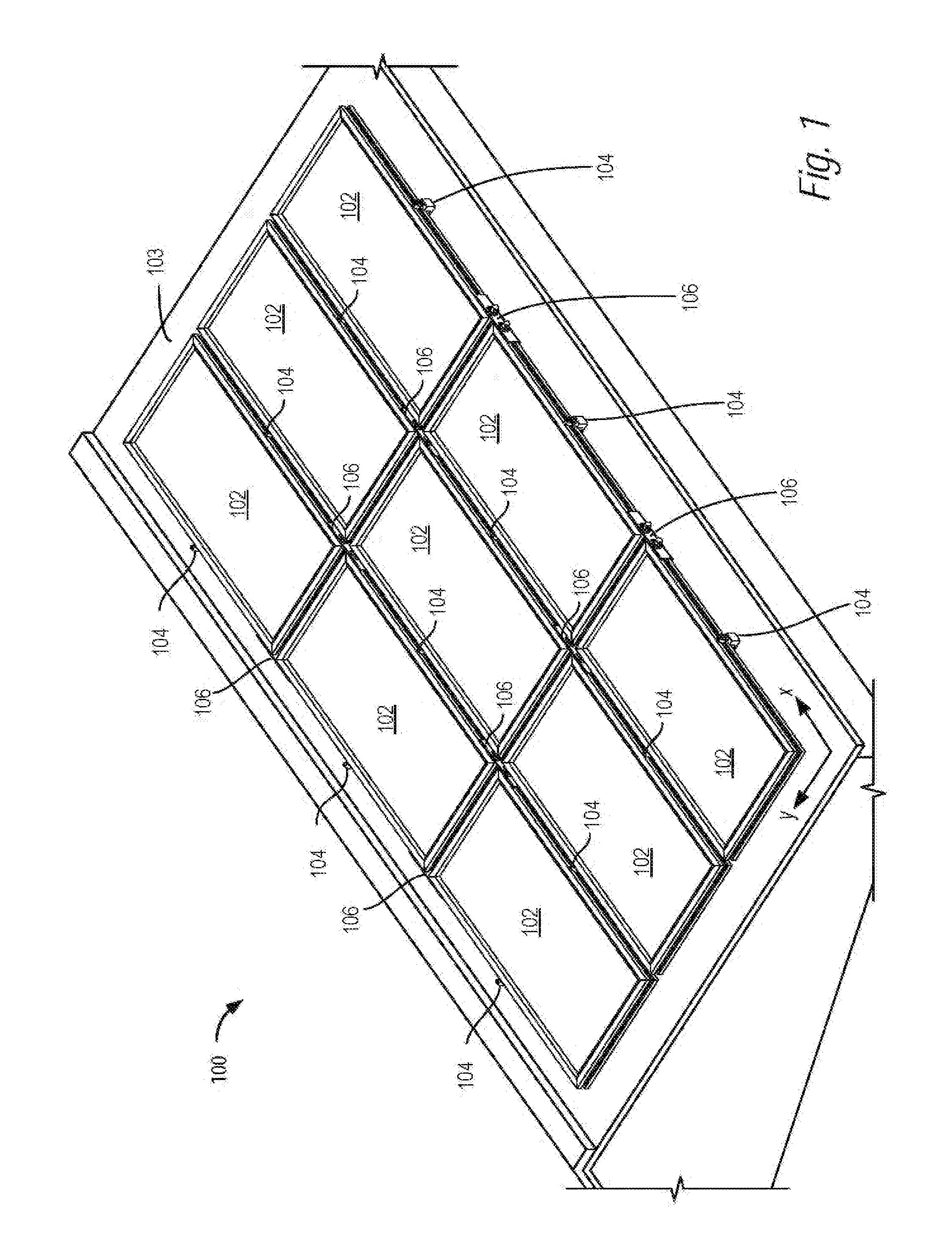
[0086]Referring now to FIG. 1, there is shown a perspective view of a PV array 100 including a plurality of PV modules 102 laid out in an x-y reference plane on a support structure 103. Mounting structure 103 is herein shown as including a planar surface, however it may be a structure with thickness, width, depth, and other dimension(s); in reference to any mounting structure, such as mounting structure 103, the height adjustment of a coupling described hereinafter is considered relative to any essential surface or essential plane, such as a top surface. The y-direction corresponds to the north-south dimension of the array, and the x-direction corresponds to the east-west direction. In the embodiment of FIG. 1, the reference plane is defined as being coextensive with a surface of the PV modules, when the PV modules are positioned in their final installed positions. However, in further embodiments, some of which are illustrated below, the reference plane may be above an upper surface...


PUM


Abstract

An apparatus and system for quickly and easily assembling PV modules into a PV array in a sturdy and durable manner. In some embodiments, the PV modules may have a grooved frame where the groove is angled into the frame with respect to the planar surface of the modules. Various components may engage within the angled groove to assemble the PV modules into the PV array using what may be referred to as a pivot-fit connection between the components and angled groove. Other embodiments may operate with PV modules having frames without angled grooves as by use of wraparound brackets.

Description

CROSS REFERENCES[0001]The present application is a continuation-in-part of copending application Ser. No. 12 / 830,250, filed Jul. 2, 2010, which claims priority to Provisional Patent Application No. 61 / 270,122, filed Jul. 2, 2009; Provisional Patent Application No. 61 / 255,004, filed Oct. 26, 2009; Provisional Patent Application No. 61 / 351,586, filed Jun. 4, 2010; and U.S. patent application Ser. No. 12 / 594,935, filed Oct. 6, 2009, which is the §371 national phase of PCT / US08 / 04569, filed Apr. 8, 2008, which PCT application claims priority to Provisional Patent Application No. 61 / 066,001, filed Feb. 15, 2008; Provisional Patent Application No. 61 / 065,417, filed Feb. 11, 2008; and Provisional Patent Application No. 60 / 922,180, filed Apr. 6, 2007. Each of the above applications is incorporated by reference herein in its entirety.[0002]This application also claims the benefit of the filing date of U.S. Provisional Patent Application Ser. No. 61 / 421,621, filed Dec. 9, 2010; and U.S. Provi...

Claims


Application Information

Patent Timeline
Patent Type & Authority Applications(United States)
IPC IPC(8): H01L31/05
CPCF24J2/5211F24J2/5245F24J2/5247F24J2/5254F24J2/5258H02S20/24F24J2/5264Y02E10/47Y02B10/12H02S20/23F24J2/5262F24S25/20F24S25/61F24S25/613F24S25/632F24S25/636F24S25/67F24S25/70F24S2025/6008Y02B10/10Y02E10/50
Inventor WEST, JOHN RAYMONDHUDSON, TYRUS HAWKESJOHANSEN, EMILATCHLEY, BRIAN
Owner TESLA INC
Why Eureka
Try Eureka