Video coding based on edge determination

a video coding and edge determination technology, applied in the field of parallel video coding techniques, can solve the problems of parallel prediction patterns, encoding and/or decoding speeds tend to decrease,

Inactive Publication Date: 2012-09-20
SHARP LAB OF AMERICA INC
View PDF4 Cites 56 Cited by
  • Summary
  • Abstract
  • Description
  • Claims
  • Application Information

AI Technical Summary

Problems solved by technology

As the computational complexity increases, the encoding and / or decoding speeds tend to decrease.
Also, parallel prediction patterns that depend solely on the number of prediction units within the block may be problematic for coding systems using other block structures because the number of prediction units may no longer correspond to the spatial size of the prediction unit.

Method used


Image

  • Video coding based on edge determination
  • Video coding based on edge determination
  • Video coding based on edge determination

Examples


Embodiment Construction

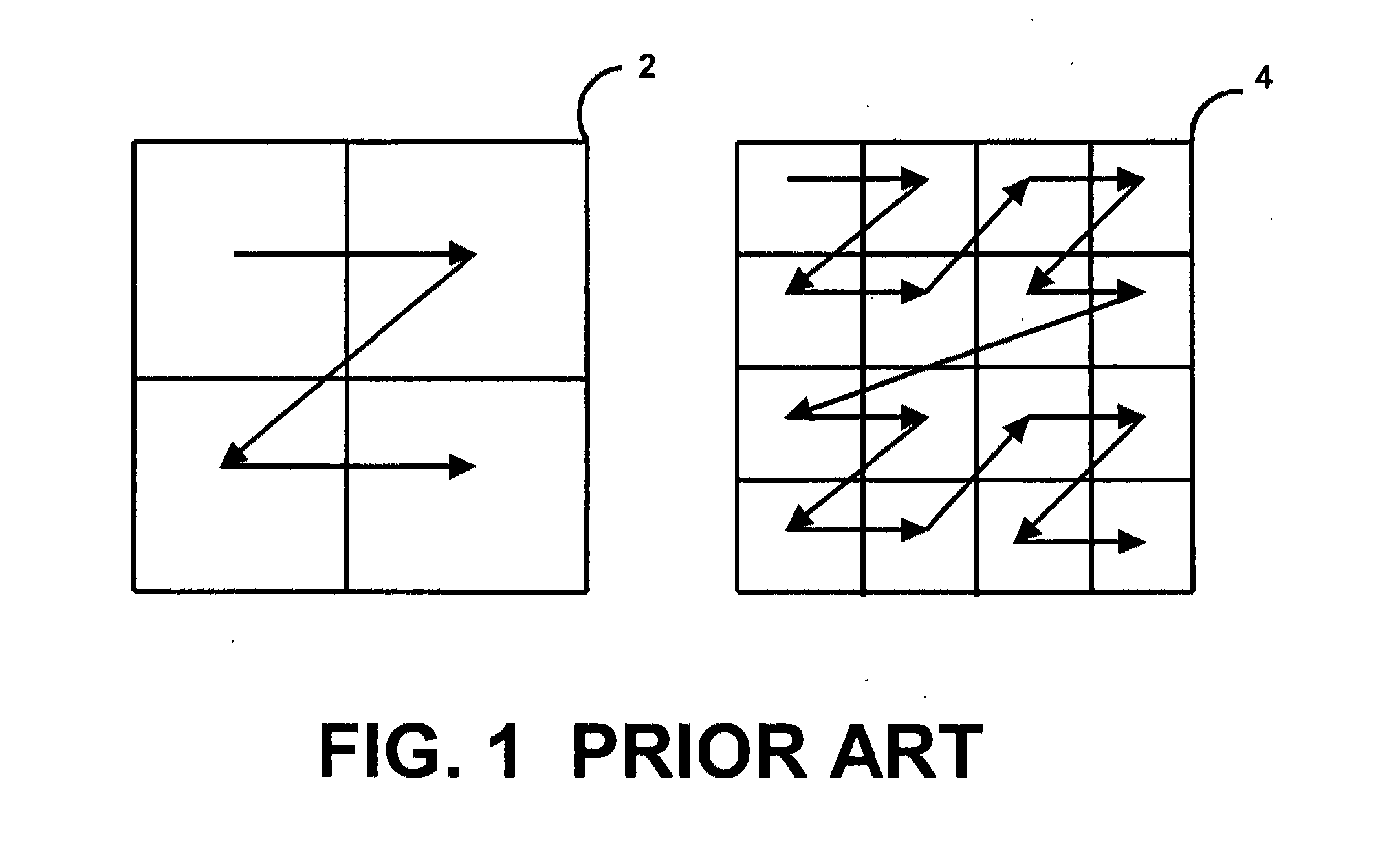
[0026]Intra-prediction based video encoding / decoding exploits spatial relationships within a frame, an image, or otherwise a block / group of pixels. At an encoder, a block of pixels may be predicted from neighboring previously encoded blocks of pixels, generally referred to as reconstructed blocks, typically located above and / or to the left of the current block, together with a prediction mode and a prediction residual for the block. A block may be any group of pixels that preferably shares the same prediction mode, the prediction parameters, the residual data and / or any other signaled data. At a decoder, a current block may be predicted, according to the prediction mode, from neighboring reconstructed blocks typically located above and / or to the left of the current block, together with the decoded prediction residual for the block. In many cases, the intra prediction uses, for example, 4×4, 8×8, 16×16, and 32×32 blocks of pixels.

[0027]Referring to FIG. 1, with respect to the H.264 / A...


PUM


Abstract

A system encoding and decoding video using intra prediction that uses an edge based determination technique together with smoothing filters.

Description

CROSS-REFERENCE TO RELATED APPLICATIONS[0001]NoneBACKGROUND OF THE INVENTION[0002]The present invention relates to a system for parallel video coding techniques.[0003]Existing video coding standards, such as H.264 / AVC, generally provide relatively high coding efficiency at the expense of increased computational complexity. As the computational complexity increases, the encoding and / or decoding speeds tend to decrease. The use of parallel decoding and parallel encoding may improve the decoding and encoding speeds, respectively, particularly for multi-core processors. Also, parallel prediction patterns that depend solely on the number of prediction units within the block may be problematic for coding systems using other block structures because the number of prediction units may no longer correspond to the spatial size of the prediction unit.BRIEF DESCRIPTION OF THE SEVERAL VIEWS OF THE DRAWINGS[0004]FIG. 1 illustrates encoding patterns.[0005]FIG. 2 illustrates prediction modes.[0006]...

Claims


Application Information

Patent Timeline
Patent Type & Authority Applications(United States)
IPC IPC(8): H04N7/26
CPCH04N19/105H04N19/46H04N19/593H04N19/436H04N19/14H04N19/44H04N19/117
Inventor SEGALL, CHRISTOPHER A.ZHAO, JIE
Owner SHARP LAB OF AMERICA INC
Why Eureka
Try Eureka