Floating fastener

Inactive Publication Date: 2012-09-20
HANWIT PRECISION IND LTD
View PDF3 Cites 34 Cited by
  • Summary
  • Abstract
  • Description
  • Claims
  • Application Information

AI Technical Summary

Benefits of technology

[0014]Further, the shoulder of the locking member is embossed, or processed to provide a pattern of teeth, ribs or raised portions, enhancing frictio

Problems solved by technology

However, during a mounting or dismounting operation, the screw nails may be lost accidentally, causing installation problems.
1. Because floating captive screw consists of the mounting socket A, the spring member A1, the stop member A3, the lock screw B and the screw nut C, it is expensive to manufacture and complicates to insta

Method used


Image

  • Floating fastener
  • Floating fastener
  • Floating fastener

Examples


Example

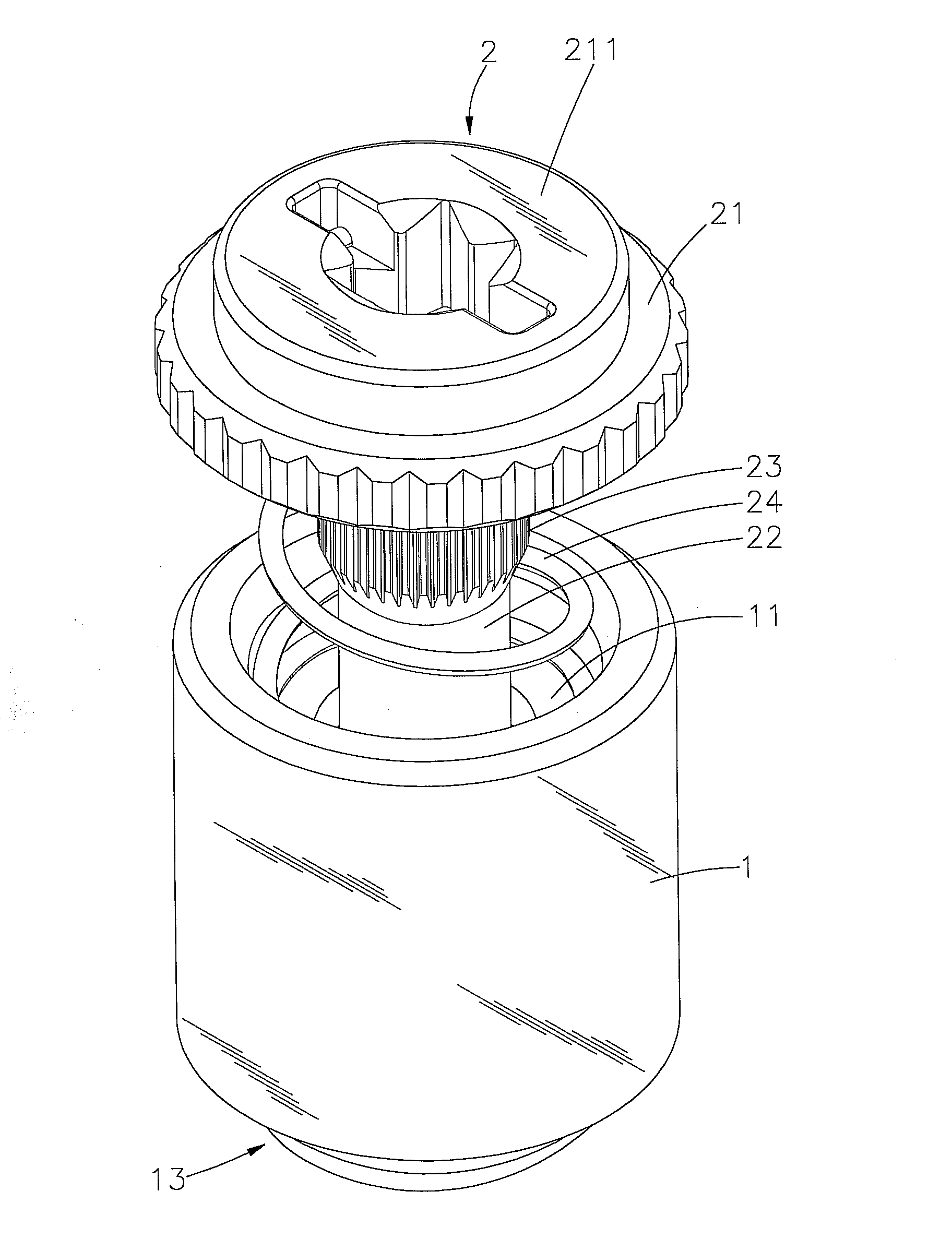
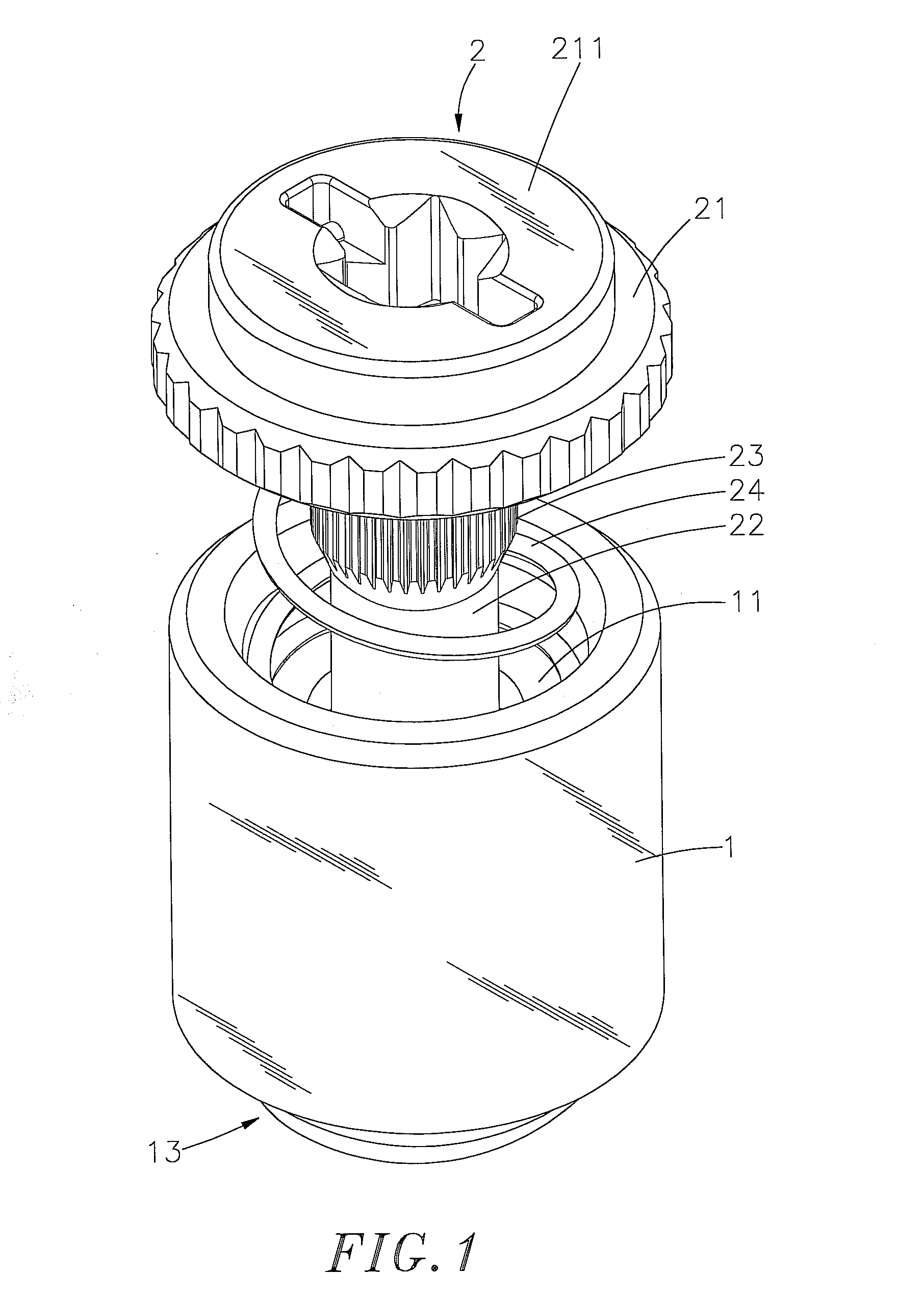
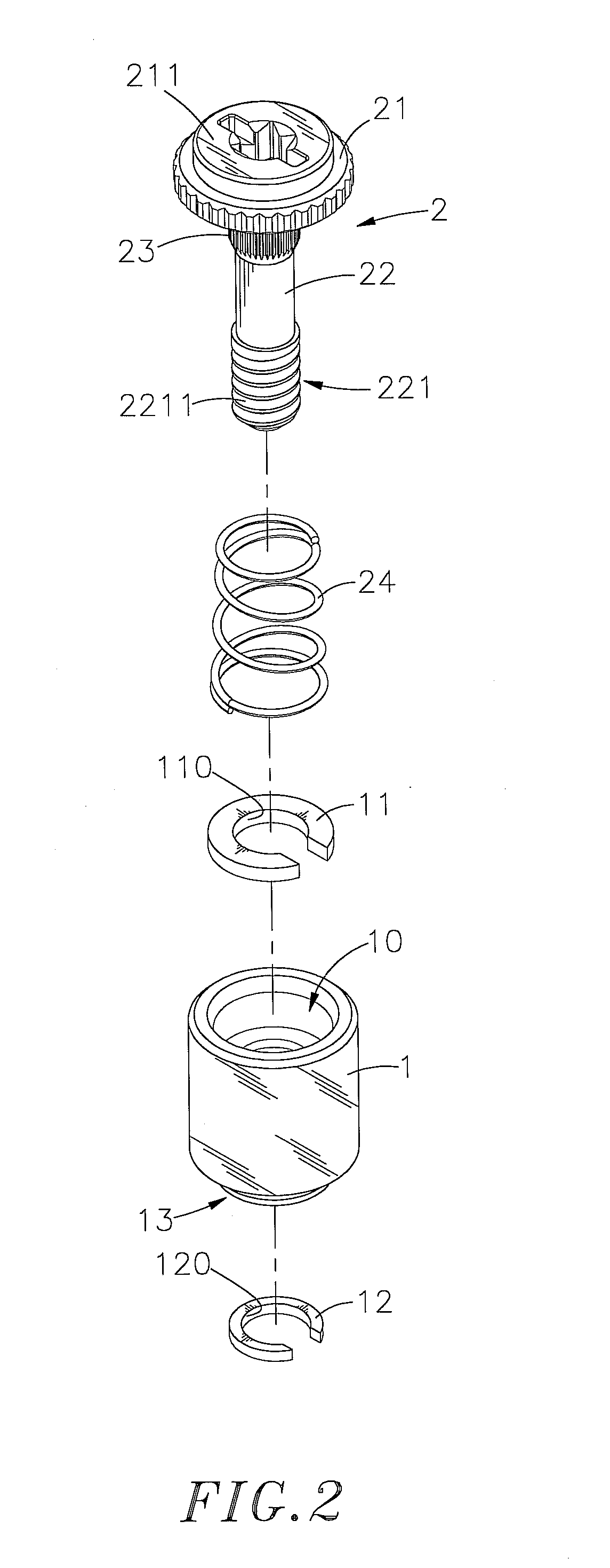
[0030]Referring to FIGS. 1˜4, a floating fastener in accordance with a first embodiment of the present invention is shown comprising a mounting socket 1, a locking member 2, a first locating ring 11, a second locating ring 12 and a spring member 24.

[0031]The mounting socket 1 comprises an open chamber 10, a first annular locating groove 101 disposed in the open chamber 10 near a top side thereof, a second annular locating groove 102 disposed in the open chamber 10 and spaced below the first annular locating groove 101, and a bottom mounting portion 13 defining a horizontally extending bonding face 131 and a vertically extending mounting neck 132.

[0032]The first locating ring 11 is a resilient or elastic member, for example, a snap ring mounted in the first annular locating groove 101 in the open chamber 10 of the mounting socket 1, defining therein a retaining hole 110.

[0033]The second locating ring 12 is a resilient or elastic member, for example, a snap ring mounted in the second ...

Example

[0042]FIGS. 7˜9 illustrate a floating fastener in accordance with a second embodiment of the present invention. This second embodiment is substantially similar to the aforesaid first embodiment with the exception of an extra cap member 3. The cap member 3 defines a bottom-open chamber 30, a top center opening 32 in communication with the bottom-open chamber 30, and a locating groove 31 extending around the inside wall thereof in the bottom-open chamber 30 and adjacent to the top center opening 32. The cap member 3 is attached to the locking member 2 to force the locating groove 31 and the tool-driving device 211 into friction engagement with the head 21 of the locking member 2. Further, the periphery of the head 21 of the locking member 2 is embossed, or processed to provide teeth, threads, ribs or raised portions, enhancing friction. Further, the bottom-open chamber 30 has a diameter greater than the outer diameter of the mounting socket 1 so that the cap member 3 can be covered on...

Example

[0044]FIGS. 10 and 11 illustrate a floating fastener in accordance with a third embodiment of the present invention. This third embodiment is substantially similar to the aforesaid second embodiment with exception of the design of the mounting socket 1 and the mounting arrangement of the first locating ring, referenced by 11, and the second locating ring 12 and the spring member 24 in the mounting socket 1. According to this third embodiment, the mounting socket 1 comprises an open chamber 10, an inside annular flange 103 transversely disposed in the open chamber 10, a first annular locating groove 101 disposed in the open chamber 10 at the bottom side of the inside annular flange 103, a second annular locating groove 102 disposed in the open chamber 10 and abutted against the bottom side of the first annular locating groove 101, and a bottom mounting portion 13 defining a horizontally extending bonding face 131 and a vertically extending mounting neck 132; a first locating ring 111...


PUM


Abstract

A floating fastener includes a mounting socket bonded to a first plate member, a locking member axially movably mounted in the mounting socket and fastenable to a second plate member to lock the first plate member to the second plate member, a first locating ring mounted in the mounting socket around a plain stem of the locking member and adapted for securing a shoulder of the locking member to hold the locking member in a received position temporarily, a spring member mounted around the locking member in the mounting socket and stopped between a head of the locking member and the first locating ring to support the locking member in a floating position, and a second locating ring mounted in the mounting socket to prohibit the locking member from falling out of the mounting socket.

Description

BACKGROUND OF THE INVENTION[0001]1. Field of the Invention[0002]The present invention relates to fasteners for joining metal plate members and more particularly, to a floating fastener, which uses a first locating ring to temporarily secure a locking member in a received position in a mounting socket thereof and a second locating ring to prohibit the locking ring from escaping out of the mounting socket, facilitating installation.[0003]2. Description of the Related Art[0004]When fastening plate members together, positioning screws that are each formed of a knob, a ring and a screw nail are usually used. During installation, the screw nail and the ring are secured to the first plate member, and then the knob is rotated to drive the screw nail into the second plate member, and then a hand tool is used to fasten tight the screw nail, affixing the first and second plate members together. This plate member joining method can be used in a machine tool to join plate members together. The p...

Claims


Application Information

Patent Timeline
IPC IPC(8): F16B21/18
CPCF16B5/0208
Inventor CHIU, MING-CHUNG
Owner HANWIT PRECISION IND LTD
Why Eureka
Try Eureka