Crane

Inactive Publication Date: 2008-02-14
CROWDER JEFFREY LEE
View PDF19 Cites 8 Cited by
  • Summary
  • Abstract
  • Description
  • Claims
  • Application Information

AI Technical Summary

Benefits of technology

[0007]The upper surfaces of the head plate and the lower surface of the foot plate preferably have engagement surfaces which will not mark the window opening, so that the crane can be used in a building without damaging any surfaces or decora

Problems solved by technology

However, windows are heavy and working with ladders in this way inevitably puts the installers at signi

Method used


Image

  • Crane
  • Crane
  • Crane

Examples


Example

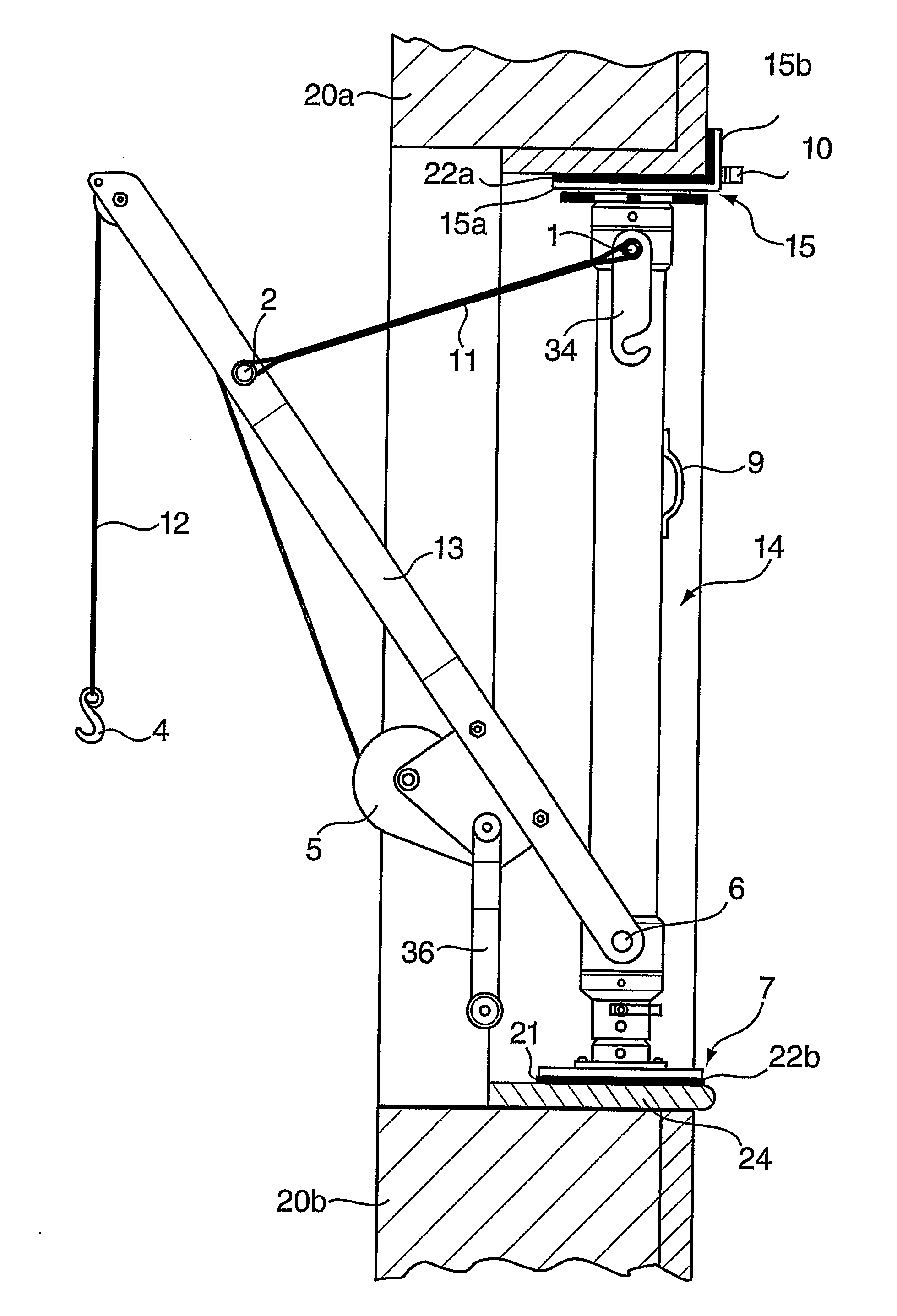
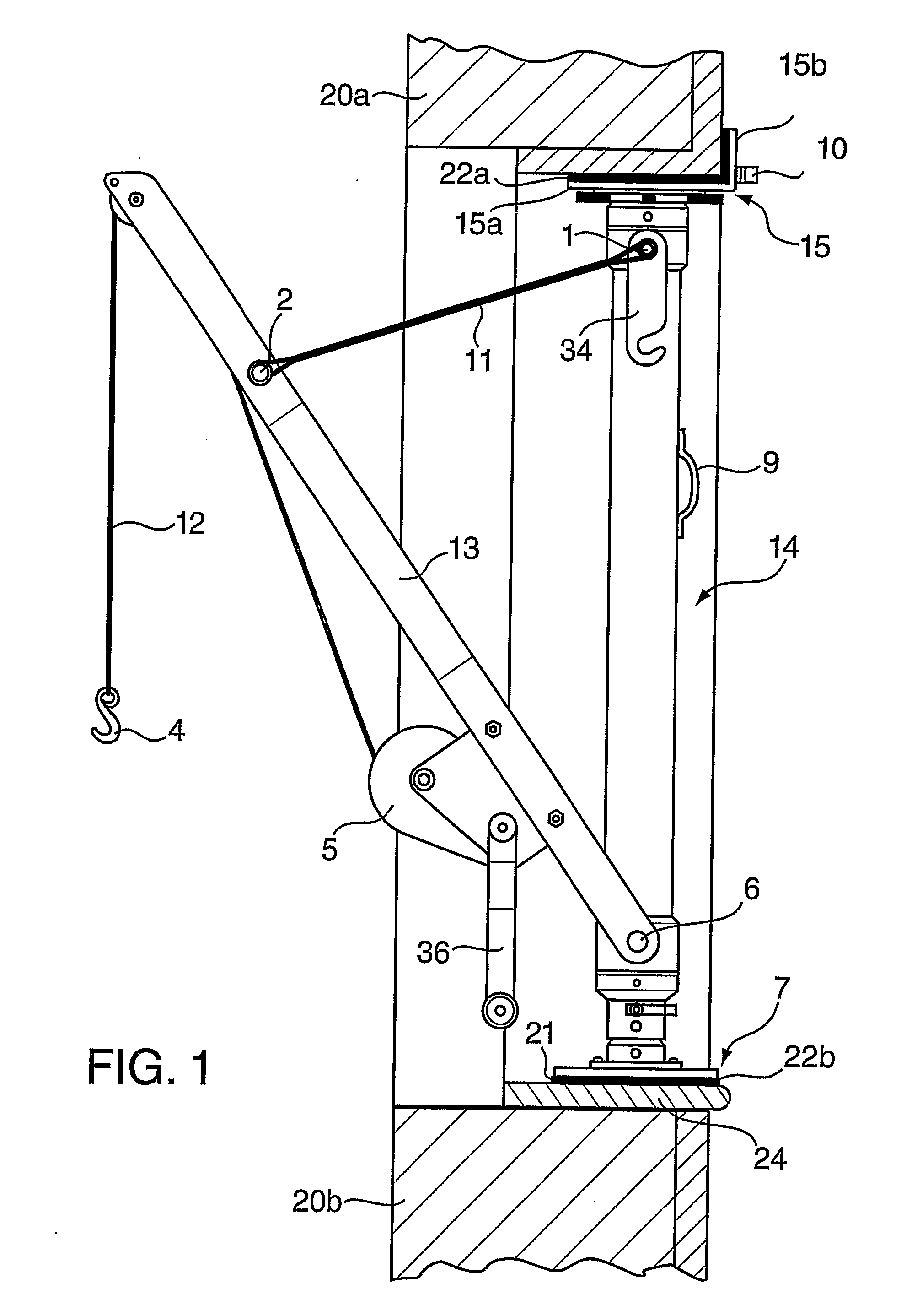
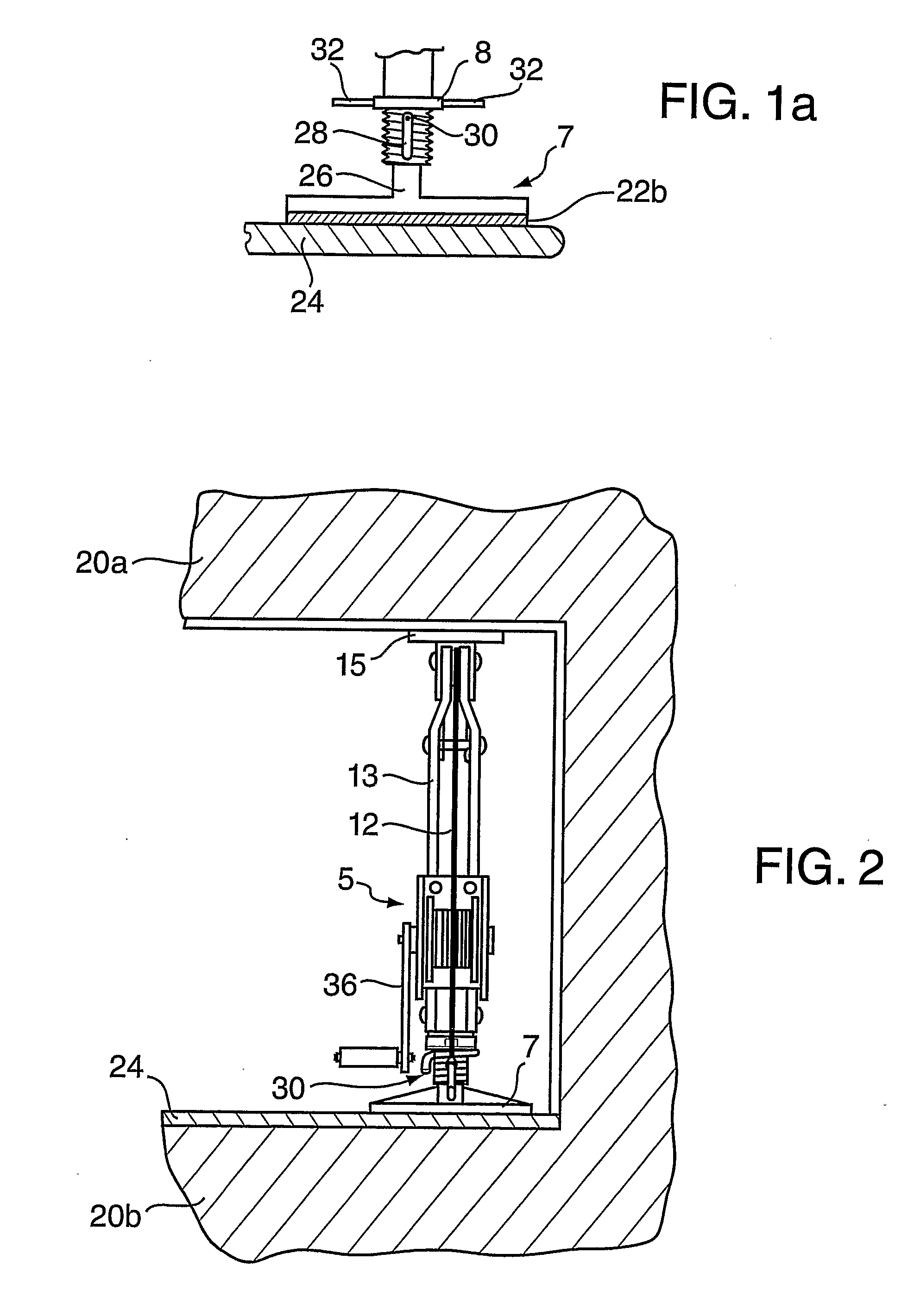
[0037]The crane of FIGS. 1 to 3 has support means comprising an elongate strut 14, a head plate 15 and a foot plate 7. The crane is installed between two fixed surfaces provided by structures 20a and 20b shown in cross-section in FIG. 1. Structures 20a and 20b define a window opening in a building, for example.

[0038]Head plate 15 provides an engagement surface 22a in contact with structure 20a, and foot plate 7 provides an engagement surface 22b in contact with a window board 24 resting on structure 20b.

[0039]Head plate 15 comprises a planar portion 15a perpendicular to the longitudinal axis of the strut 14 and a portion 15b upstanding from portion 15a, which extends parallel to that axis. As shown in FIG. 1, head plate portion 15b is arranged to engage an internal vertical surface of the structure 20a.

[0040]The planar engagement surface 22b of foot plate 7 extends in a plane perpendicular to the longitudinal axis of strut 14. A slippage resistant cushioning material 21, such as r...


PUM


Abstract

A crane to be fitted in a window opening or the like, between two opposing surfaces, has a strut (14) which is first braced between the surfaces (20a, 20b), and a boom (13) which extends away from the strut. A winch (5) on the crane winds up a lifting cafe (12) which runs over a pulley (3) at the outer end of the boom (13). The top and bottom ends of the strut have end plates (15, 7) which are designed to hold the crane rigidly between the two surfaces, but without damaging any surface finish on either surface. The boom (13) can be swung about the axis of the strut (14) to bring the load carried by the crane in towards the position of the operator.

Description

BACKGROUND[0001]a. Field of the Invention[0002]The present invention relates to a crane. More particularly, it concerns a crane suitable for assisting the installation of windows in a building.[0003]b. Related Art[0004]Windows are often fitted to a building by carrying them up a ladder, and then installing them whilst standing on the ladder. However, windows are heavy and working with ladders in this way inevitably puts the installers at significant risk. Alternatively, scaffolding may be used, but this is time consuming and costly to construct.SUMMARY OF THE INVENTION[0005]According to a first aspect of the invention, there is provided a crane for use in raising windows into place in a window opening in a building, the crane comprising an adjustable length strut having a head plate at one end and a foot plate at the other end and a boom mounted on the strut, the head plate having two faces substantially at right angles to one another for engagement with two surfaces of an edge of a...

Claims


Application Information

Patent Timeline
IPC IPC(8): B66C23/22
CPCB66C23/22
Inventor CROWDER, JEFFREY LEE
Owner CROWDER JEFFREY LEE
Why Eureka
Try Eureka