In-situ clean process for metal deposition chambers

a technology for metal deposition chambers and cleaning methods, applied in vacuum evaporation coatings, chemical vapor deposition coatings, coatings, etc., can solve the problems of large amount of ongoing effort, defect of barrier layer, and difficult filling of submicron structures of deposition processes

Inactive Publication Date: 2012-09-20
APPLIED MATERIALS INC
View PDF6 Cites 23 Cited by
  • Summary
  • Abstract
  • Description
  • Claims
  • Application Information

AI Technical Summary

Problems solved by technology

However, as the fringes of circuit technology are pressed, the shrinking dimensions of interconnects in VLSI and ULSI technology have placed additional demands on the processing capabilities.
Many traditional deposition processes have difficulty filling submicron structures where the aspect ratio exceeds 4:1.
Therefore, there is a great amount of ongoing effort being directed at the formation of substantially void-free and seam-free and conformal submicron features having high aspect ratios.
When the accumulated deposition by-products reach a certain thickness, the deposition by-products may peel off or flake off from the inner wall and contaminate the barrier layer by falling onto the substrate, causing defects to the barrier layer.
However, some metallic compounds require high temperature to be efficiently removed from the chamber components, and operation at such temperatures is not readily feasible in due to seal service temperature limitations for most chambers currently utilized by integrated circuit fabricators.

Method used


Image

  • In-situ clean process for metal deposition chambers
  • In-situ clean process for metal deposition chambers
  • In-situ clean process for metal deposition chambers

Examples


Embodiment Construction

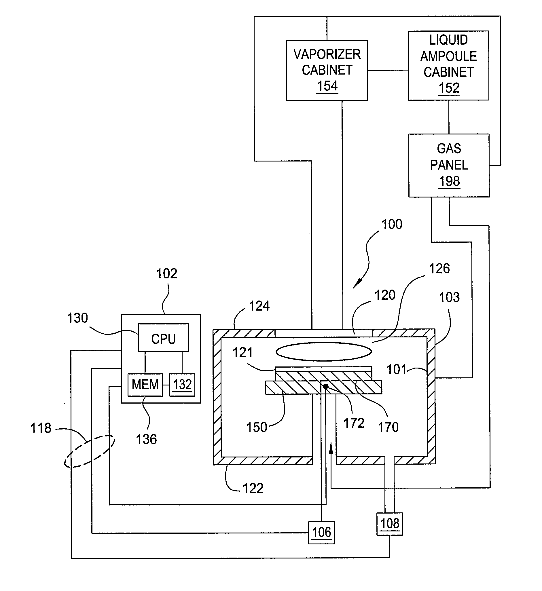
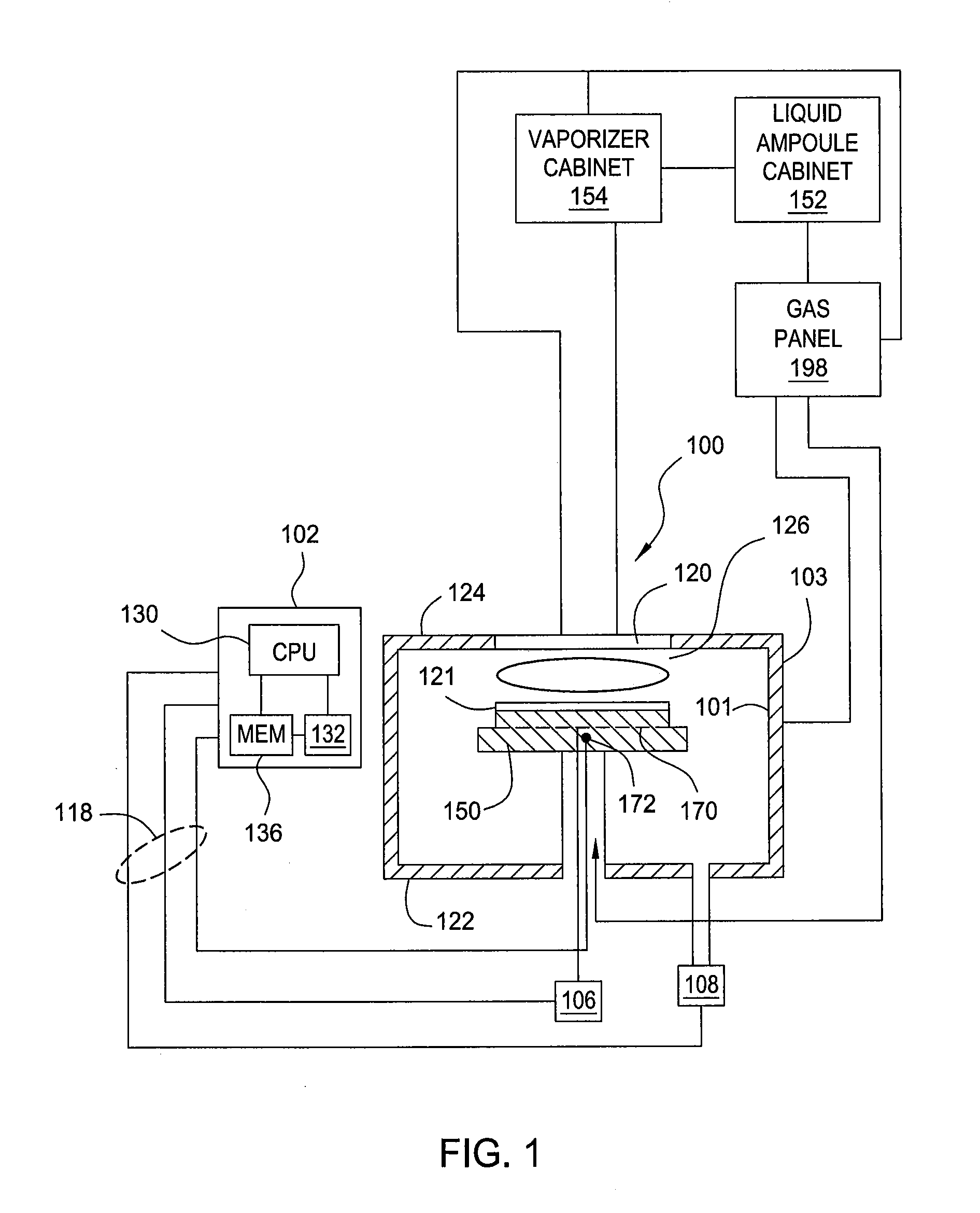
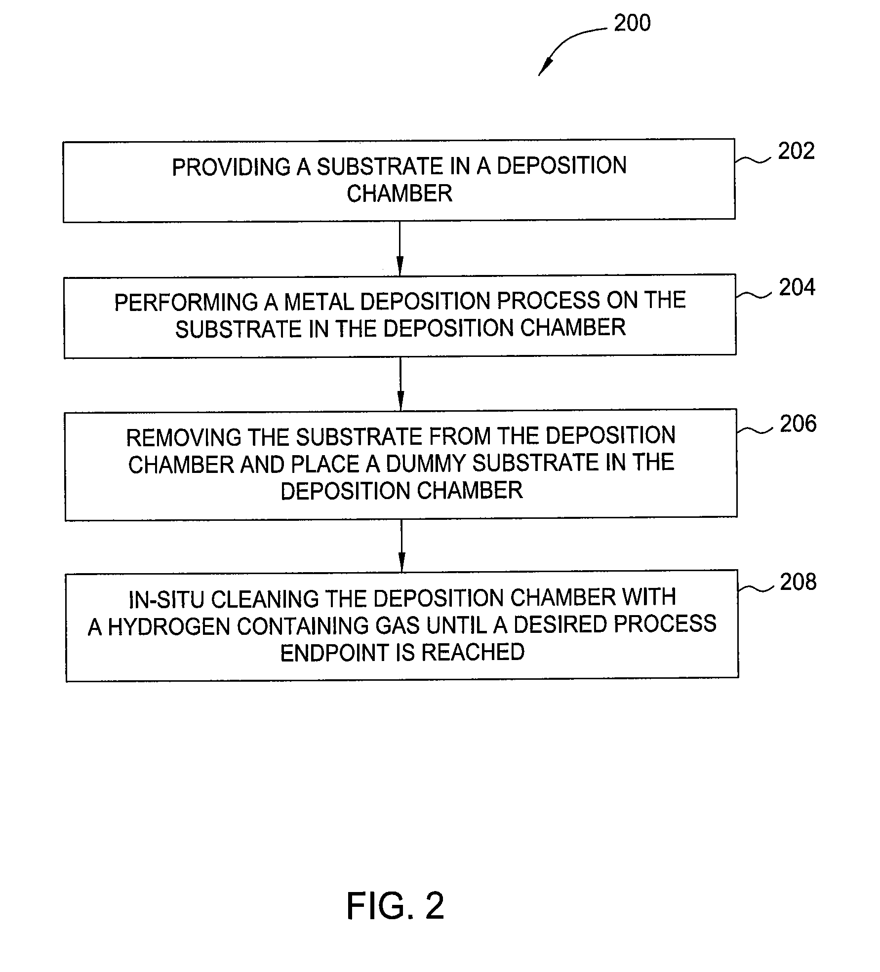
[0019]Embodiments of the present invention provide methods and apparatus for in-situ chamber cleaning for metal deposition chambers. The deposition by-products accumulated on the chamber walls or chamber components may be efficiently removed by performing an in-situ cleaning process to remove deposition by-products from the deposition chambers. In one embodiment, the in-situ cleaning process may be performed by providing a dummy substrate in the processing chamber while supplying a hydrogen containing gas into the processing chamber to react with deposition by-products formed on the chamber components. After reaction, the deposition by-products may become brittle and tend to flake off from the chamber walls, falling on the dummy substrate. Subsequently, the dummy substrate is removed from the processing chamber as well as the embrittled deposition by-product particles disposed thereon.

[0020]FIG. 1 depicts one embodiment of a metal deposition chamber 100 that may be used to deposit a...


PUM

PropertyMeasurementUnit
poweraaaaaaaaaa
poweraaaaaaaaaa
pressureaaaaaaaaaa

Abstract

Embodiments of the invention include methods for in-situ chamber dry clean for metal deposition chambers. In one embodiment, a method for in-situ chamber dry clean after a metal deposition process includes placing a substrate in a processing chamber, performing a metal deposition process on the substrate in the processing chamber, removing the substrate from the support pedestal, and performing an in-situ cleaning process by supplying a cleaning gas containing H2 to the processing chamber while a dummy substrate is disposed in the processing chamber

Description

CROSS REFERENCE TO RELATED APPLICATIONS[0001]This application claims benefit of U.S. Provisional Patent Application No. 61 / 453,934, filed Mar. 17, 2011, which is incorporated by reference in its entirety.BACKGROUND[0002]1. Field[0003]Embodiments of the present invention generally relate to method and apparatus for cleaning a processing chamber. Particularly, embodiments of the present invention relate to methods and apparatus for in-situ cleaning a processing chamber for metal deposition applications.[0004]2. Description of the Related Art[0005]Reliably producing submicron and smaller features is one of the key technologies for the next generation of very large scale integration (VLSI) and ultra large scale integration (ULSI) of semiconductor devices. However, as the fringes of circuit technology are pressed, the shrinking dimensions of interconnects in VLSI and ULSI technology have placed additional demands on the processing capabilities. The multilevel interconnects that lie at th...

Claims


Application Information

Patent Timeline
Patent Type & Authority Applications(United States)
IPC IPC(8): B05D3/06B05D3/14B05D3/04
CPCC23C16/4405
Inventor JACKSON, MICHAELSUH, SONG-MOONSUNDARAJJAN, ARVINDNARASIMHAN, MURALI K.THIRUNAVUKARASU, SRISKANTHARAJAH
Owner APPLIED MATERIALS INC
Why Eureka
Try Eureka