Electrostimulator capable of outputting stable electric stimulus

a technology of electric stimulus and electric stimulus, which is applied in the field of electro-stimulators, can solve the problems of difficult walking difficult dorsiflexion of ankle joints for patients with drop-foot, etc., and achieve the effect of stable voluntary myoelectric potential and stable electric stimulus

Inactive Publication Date: 2012-09-20
HEALTH SCI TECH TRANSFER CENT JAPAN HEALTH SCI FOUND
View PDF0 Cites 23 Cited by
  • Summary
  • Abstract
  • Description
  • Claims
  • Application Information

AI Technical Summary

Benefits of technology

[0033]According to the present invention there is provided an electrostimulator capable o...

Problems solved by technology

Dorsiflexion of an ankle joint is difficult for a patient with drop-foot because of a weakness in the dorsiflexion muscle gro...

Method used


Image

  • Electrostimulator capable of outputting stable electric stimulus
  • Electrostimulator capable of outputting stable electric stimulus
  • Electrostimulator capable of outputting stable electric stimulus

Examples


first embodiment

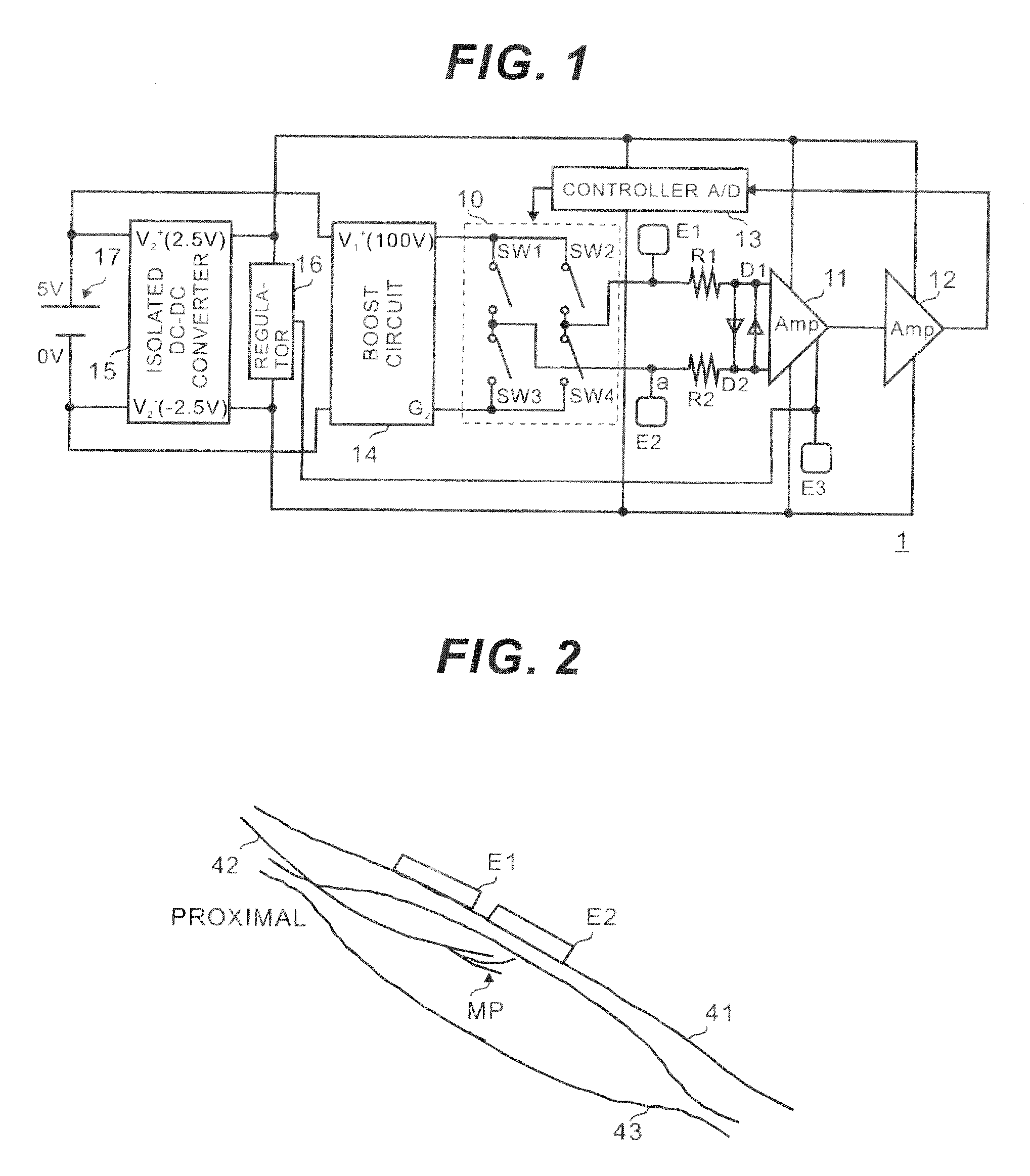
[0046]FIG. 1 is a circuit diagram showing a structure of an electrostimulator 1 according to the present invention.

[0047]The electrostimulator 1 mainly consists of an isolated DC-DC converter 15, electrodes E1, E2 and E3, protective resistors R1 and R2, diodes D1 and D2, a instrumentation amplifier 11, a multi-step amplifier 12, a controller 13, a boost circuit (step-up circuit) 14, an H-bridge circuit 10 and a regulator 16.

[0048]A high voltage (100V) is obtained by boosting an output of a battery (5V) 17, and simultaneously the battery (5V) 17 supplies power to the amplifiers 11 and 12 and the controller 13 via the isolated DC-DC converter 15. Moreover, a reference voltage is generated by the regulator 16.

[0049]In this embodiment, My Battery Lite manufactured by Japan Trust Technology, INC. is used as the battery 17. The battery 17 is not limited to that product but various types of batteries such as an external battery used for a mobile phone can be used. The electrostimulator 1 c...

second embodiment

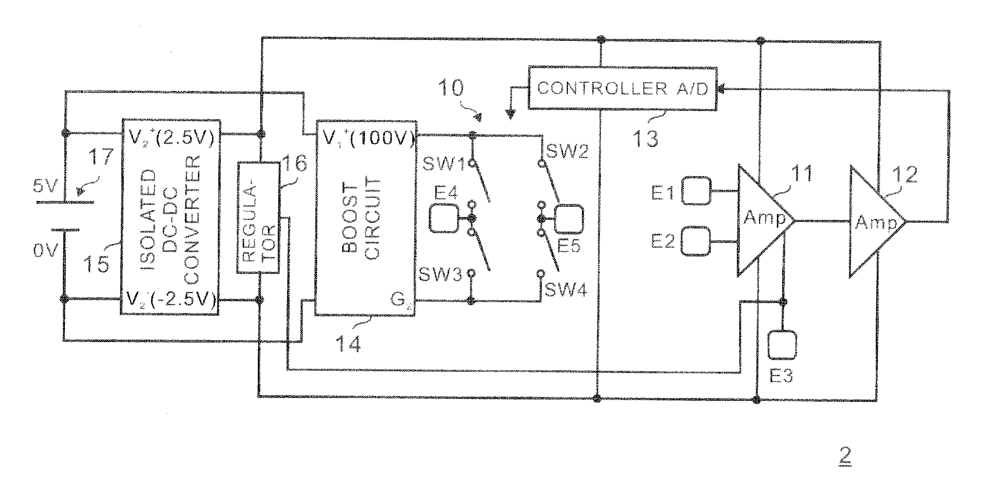
[0082]FIG. 5 is a circuit diagram showing a structure of an electrostimulator 2 according to the present invention.

[0083]The second embodiment is different from the first embodiment in that the electrodes E1 and E2 functions only as recording electrodes and electrodes E5 and E6 are added as stimulus electrodes. Other structures are similar to the first embodiment and so the explanations for those will be omitted.

[0084]In this embodiment also the stimulus is not applied to the electrode E3, and so stable output of the stimulus can be obtained by supplying the high voltage continuously.

[0085]In the second embodiment, the detection of the voluntary myoelectric signal and application of the electric stimulus can be performed on the different positions (on different muscles including muscles of other person). For example, in case of using the electrostimulator 2 according to this embodiment for a patient with facial nerve paralysis, the electrodes E1 and E2 can be disposed on a normal si...

third embodiment

[0087]In the electrostimulator 3 a diac D3 (fifth switch) is connected between the common terminal of the photoMOS relays SW2 and SW4 and the electrode E4, and a diac D4 (sixth switch) is connected between the common terminal of the photoMOS relays SW2 and SW4 and the electrode E5. Moreover, the electrode E6 disposed on a skin surface is connected to the common terminal of the photoMOS relays SW1 and SW3, to the reference terminal of the amplifier 11 and to the output terminal of the regulator 16. By using diacs for the fifth and sixth switches, the electrostimulator 3 is further miniaturized.


PUM


Abstract

An electrostimulator comprises a boost circuit supplying a stimulus signal, first and second electrodes disposed on a skin surface, detecting a voluntary myoelectric signal and giving the stimulus signal, an amplification circuit amplifying the voluntary myoelectric signal, a controller controlling the stimulus signal in accordance with the voluntary myoelectric signal, an H-bridge circuit comprising first and third switches connected in series and connected to the second electrode, and second and fourth switches connected in series and connected to the first electrode, the first to the fourth switches being connected in parallel, an isolated DC-DC converter supplying a power to the controller and the amplification circuit, a regulator outputting a midpoint voltage of a power-supply voltage, and a third electrode connected to the regulator and a reference terminal of the amplification circuit and disposed on the skin surface.

Description

[0001]This application is based on Japanese Patent Application 2009-254973, filed on Nov. 6, 2009, and International Application PCT / JP2010 / 006408, filed on Oct. 29, 2010, the entire contents of which are incorporated herein by referenceBACKGROUND OF THE INVENTION[0002]A) Field of the Invention[0003]This invention relates to an electrostimulator, and more specifically relates to an electro stimulator which is ideal for assisting or recovering motor functions or strengthening of muscular power of a patient who has had a cerebrovascular accident or the likes.[0004]B) Description of the Related Art[0005]There is known “drop-foot” as a sequela of hemiplegia caused by a cerebrovascular accident. Dorsiflexion of an ankle joint is difficult for a patient with drop-foot because of a weakness in the dorsiflexion muscle group and hyperfunction of the plantarflexion muscle group. Therefore, in swing phase of walking, a healthy person can smoothly move a foot forward by dorsiflexion of an ankle...

Claims


Application Information

Patent Timeline
IPC IPC(8): A61N1/36
CPCA61N1/36014A61N1/36003A61N1/36031A61N1/36034
Inventor MURAOKA, YOSHIHIRO
Owner HEALTH SCI TECH TRANSFER CENT JAPAN HEALTH SCI FOUND
Why Eureka
Try Eureka