Composite grille louvers

a technology of composite grille and louvers, which is applied in the direction of protective equipment, armoured vehicles, weapons, etc., can solve the problems of projectile damage to the engine or other components, air can easily flow through the non-linear path, and projectiles cannot easily navigate the non-linear path, so as to maintain improve the protective ability of the grille, and improve the airflow through the circuitous path

Inactive Publication Date: 2012-09-27
BAE SYSTEMS LAND & ARMAMENTS LP
View PDF16 Cites 15 Cited by
  • Summary
  • Abstract
  • Description
  • Claims
  • Application Information

AI Technical Summary

Benefits of technology

[0008]The present invention is directed to a grille having louvers shaped to increase the efficiency of air flow through the grille without decreasing the effectiveness of the louvers at stopping or deflecting projectiles. Each louver comprises an S-shape with a hooked portion at the end of the louver to present a ballistic hook for stopping projectiles ricocheting through the circuitous path defined between the louvers. An insert comprising a foam core and covered by a closeout is positioned within each hooked shape portion. The insert fills in the inlet in the louver created by the hooked shape portion to define a continuous S-shape to eliminate the eddy or stall created at the end of the circuitous path by the hooked shape portion. Alternatively, the inlet can be enclosed by the closeout to define an air pocket within the inlet. The closeout can be penetrated by projectiles ricocheting through the circuitous path such that the ballistic hook can capture the projectile within the inlet.
[0009]A grille, according to an embodiment of the present invention, comprises a plurality of S-shaped louvers arranged in an overlapping configuration to define a plurality of circuitous paths between the louvers through the grille. Each louver comprises a hooked shaped portion at one end defining an inlet and a ballistic hook generally perpendicular to the circuitous path. An insert comprising a foam core can be positioned within an inlet. The insert can be shaped to “fill in” the inlet to prevent the ballistic hook from creating eddies or stalls as air flows through the circuitous path. The insert can further comprise a closeout comprising a material positioned over the foam core to provide a continuous surface creating a smooth air flow. Alternatively, the closeout can be positioned over the inlet with a foam core so as to define an air pocket within the inlet.
[0010]In one aspect, a plurality of hardened bars can be positioned in front of the louvers to fragment or degrade incoming projectiles before the projectiles reach the louvers. Similarly, in one aspect, an open honeycomb mesh can be positioned behind to capture the remaining projectile fragments that ricochet through circuitous path and are not captured by the ballistic hooks of the louvers. In this aspect, the louvers can comprise a low weight composite material to offset the increased weight from the bars and mesh.
[0011]In one aspect, a method of preventing projectiles from entering a vent comprising the steps of positioning a plurality of S-shaped louvers in the vent, wherein each louver comprises a hook shape portion defining an inlet and a ballistic hook oriented to capture projectiles at one end of the louver. The method further comprises arranging the S-shaped louvers in an overlapping arrangement to define a plurality of circuitous routes between the louvers for the passage of air through the vent. Finally, the method comprises positioning an insert within the inlet to enclose the ballistic hook to prevent disruption of the air flow through the circuitous path, wherein the insert comprises a lower density material than the louver such that the projectile can penetrate the insert and be captured within by the ballistic hook.

Problems solved by technology

However, if a projectile enters the vent, the projectile can damage the engine or other components.
Although the projectiles cannot easily navigate the non-linear paths defined by the louvers, air can easily flow through the non-linear paths.
The inherent tradeoff with a louver protected vent is that improving protection for the vent typically worsens the air flow through the vent.
The slowed air supply can hinder the performance of the engine components supplied by the vent.
However, reducing the number of louvers to increase the cross-sectional area of the circuitous paths increases the likelihood that a projectile will penetrate the grille and enter the engine compartment.
However, the inlet and ballistic hook defined by the hooked shaped portion can create a stall or eddy in the air flow through the circuitous path upsetting the smooth air flow through the grille and creating a large pressure drop across the vent.
A similar tradeoff is that increasing the size or number of louvers can increase the weight and profile of the grille.
However, the drawback of the bars is that the bars significantly increase the weight and profile of the grill.

Method used


Image

  • Composite grille louvers
  • Composite grille louvers
  • Composite grille louvers

Examples


Embodiment Construction

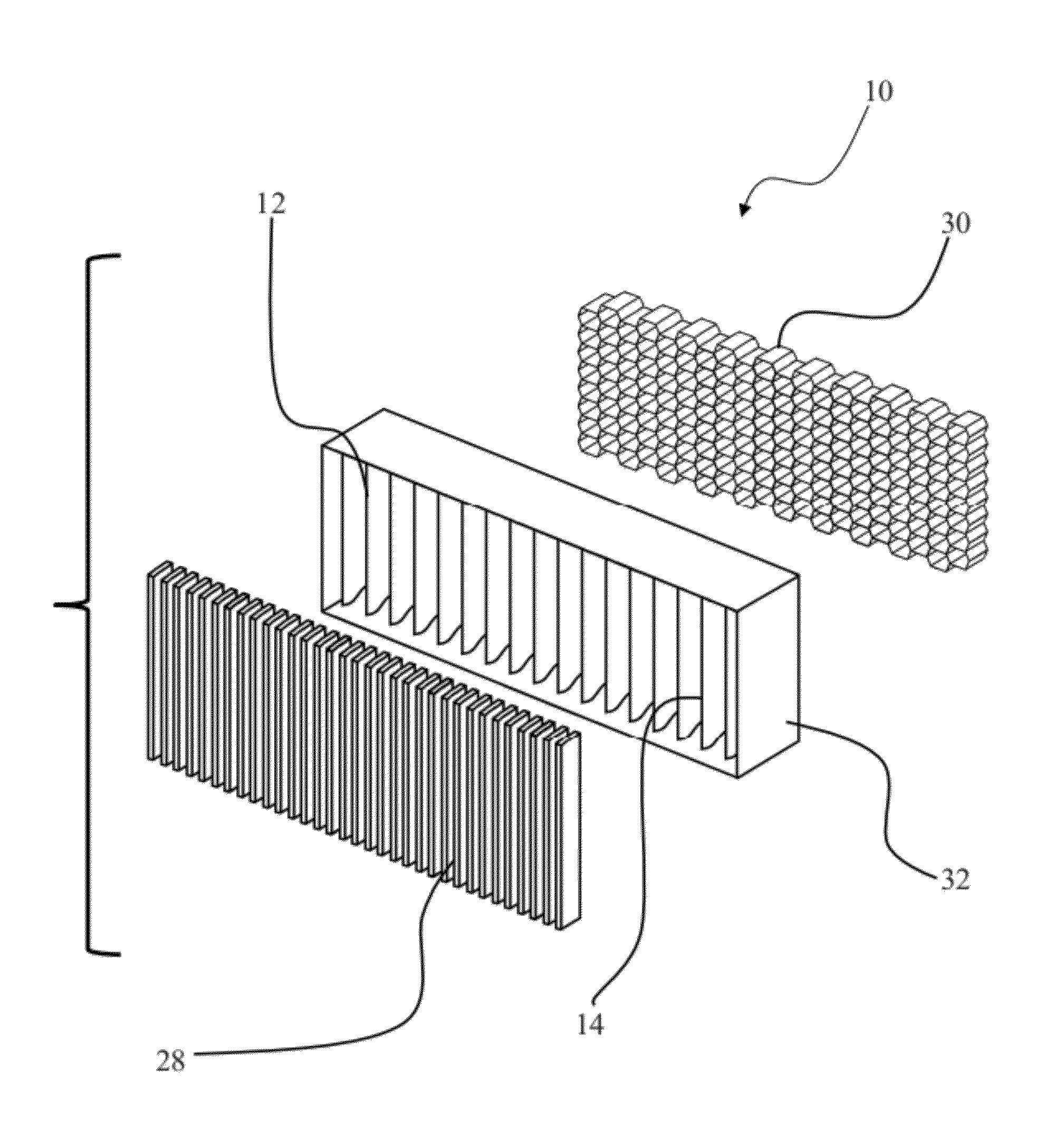
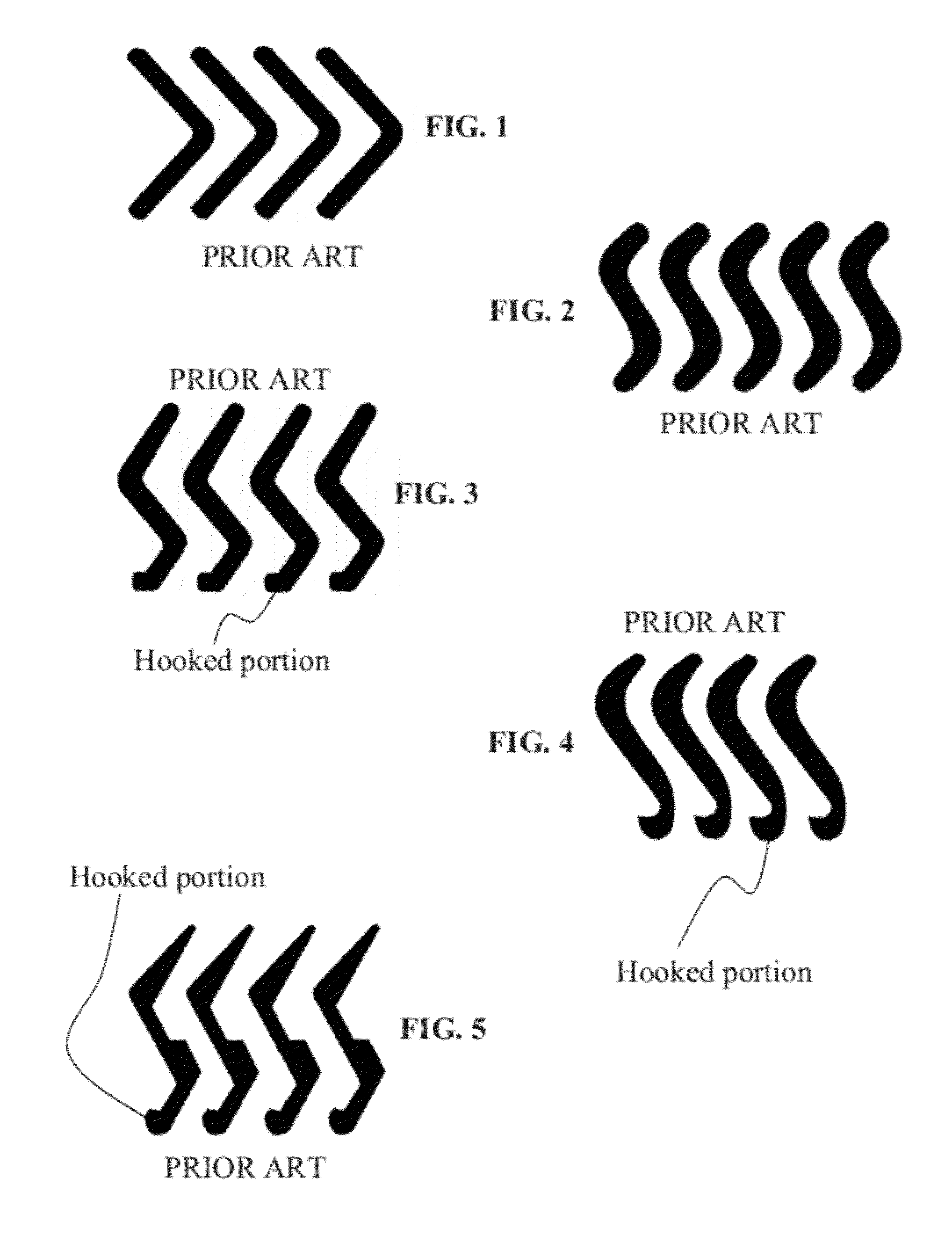
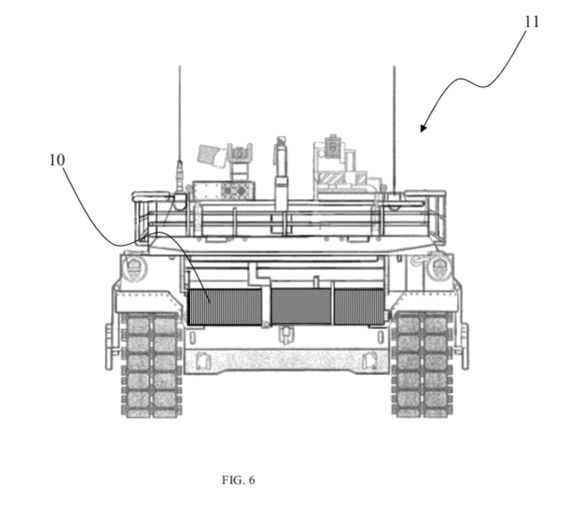
[0025]As shown in FIGS. 6-9, a grille 10, according to an embodiment of the present invention, comprises a plurality of S-shaped louvers 12 each having an exterior end 14 and an interior end 16. In one aspect, the exterior end 14 can comprise a tapered shape to minimize disruption of the airflow through the grille 10. The interior end 16 further comprises a hooked portion 18 defining an inlet 20 in the louver 12 and a ballistic hook 22 generally perpendicular to the louver 12. Each louver 12 further comprises an insert 22 shaped to fit within the inlet 20 and comprising a foam core 24 and a closeout 26. In another aspect, the louver 12 can only comprise the closeout 26 to define an air pocket in the inlet 20. In one aspect, the louvers can be about 3 inches long.

[0026]In one aspect, the louvers 12 can comprise a composite material rather than a metal to reduce the overall weight of the grille 10 while improving the ballistic protection of the grille 10. The composite material can ca...


PUM


Abstract

A grille having a plurality of s-louvers shaped to increase the efficiency of air flow through the grille without decreasing the effectiveness of the louvers at stopping or deflecting projectiles. Each louver has a hooked portion at the end of the louver to present a ballistic hook for stopping projectiles ricocheting through the circuitous path defined between the louvers. An insert having a closeout for covering the ballistic hook is positioned within each hooked shape portion to eliminate the eddy or stall created at the end of the circuitous path by ballistic hook. The closeout can be penetrated by projectiles ricocheting through the circuitous path such that the ballistic hook can still capture projectiles within the inlet.

Description

RELATED APPLICATION[0001]The present application claims the benefit of U.S. Provisional Application No. 61 / 467,605 entitled “COMPOSITE GRILLE LOUVERS, filed Mar. 25, 2011, which is incorporated herein in its entirety by reference.FIELD OF THE INVENTION[0002]The present invention is generally directed to ballistic louvers permitting the flow of air through a vent while preventing projectiles from entering the vent. Specifically, the present invention is directed to ballistic louvers for improving air flow through the vent while maintaining ballistic projection.BACKGROUND OF THE INVENTION[0003]Armored vehicles often have intake exhaust vents for supplying air to engine components and other systems. However, if a projectile enters the vent, the projectile can damage the engine or other components. A grille having a plurality of louvers is commonly fitted to the intake exhaust vents to prevent projectiles from entering the engine compartment while permitting air to flow between the louv...

Claims


Application Information

Patent Timeline
Patent Type & Authority Applications(United States)
IPC IPC(8): F41H5/02F41H7/00
CPCF41H5/026
Inventor SCHADE, DAVID ARTHURPIKE, TORREYTHOMAS, GEORGENGUYEN, QUANIWEN, MIKE
Owner BAE SYSTEMS LAND & ARMAMENTS LP
Why Eureka
Try Eureka