

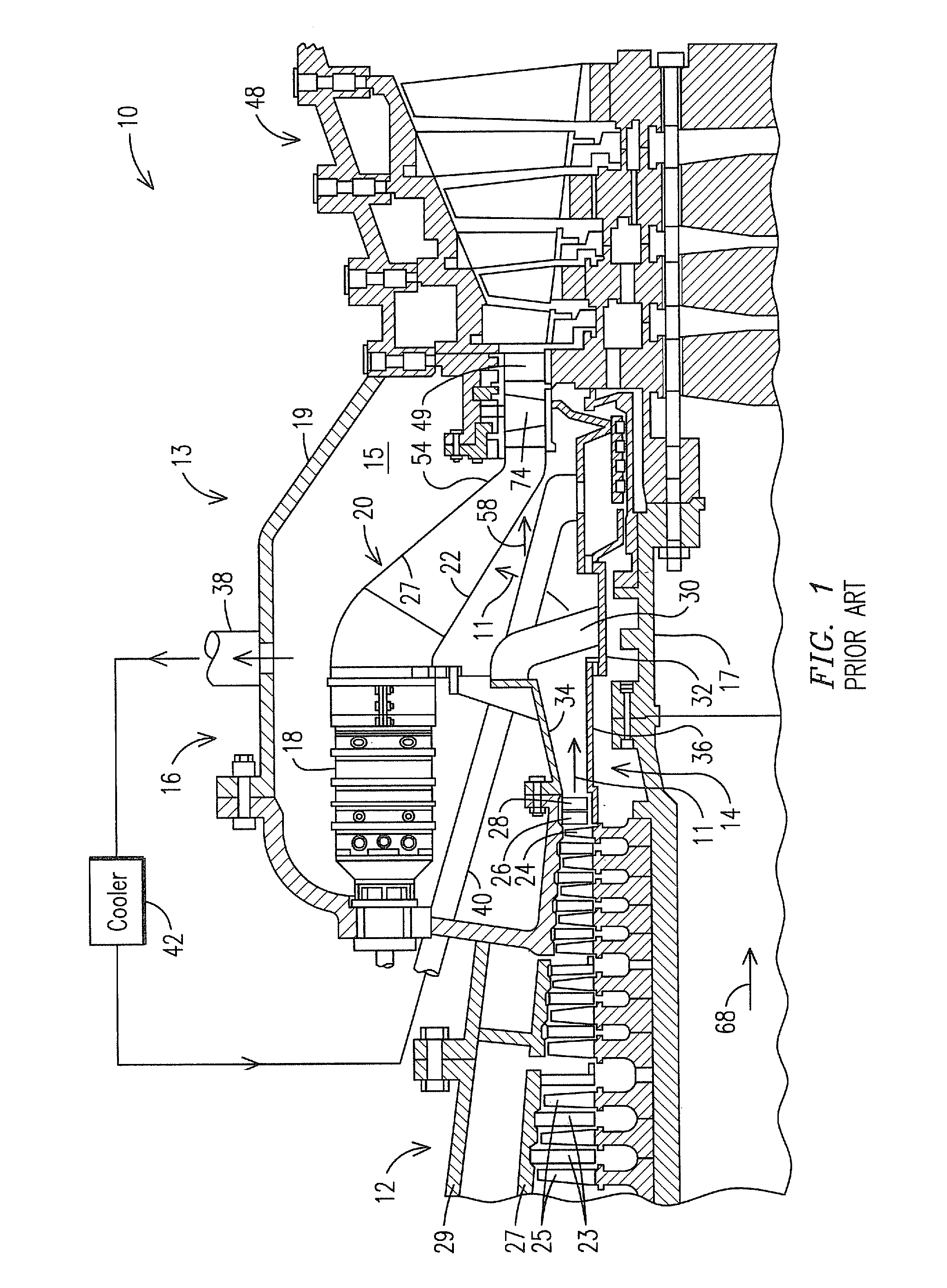
Mid-section of a can-annular gas turbine engine with a radial air flow discharged from the compressor section
a gas turbine engine and compressor technology, applied in liquid fuel engines, machines/engines, lighting and heating apparatus, etc., can solve the problems of fluid friction induced pressure loss, flow turbulence, etc., to improve the cost efficiency of can annular gas turbine engines, minimize such losses, and improve overall engine performance
- Summary
- Abstract
- Description
- Claims
- Application Information
AI Technical Summary
Benefits of technology
Problems solved by technology
Method used
Image

Examples
Embodiment Construction
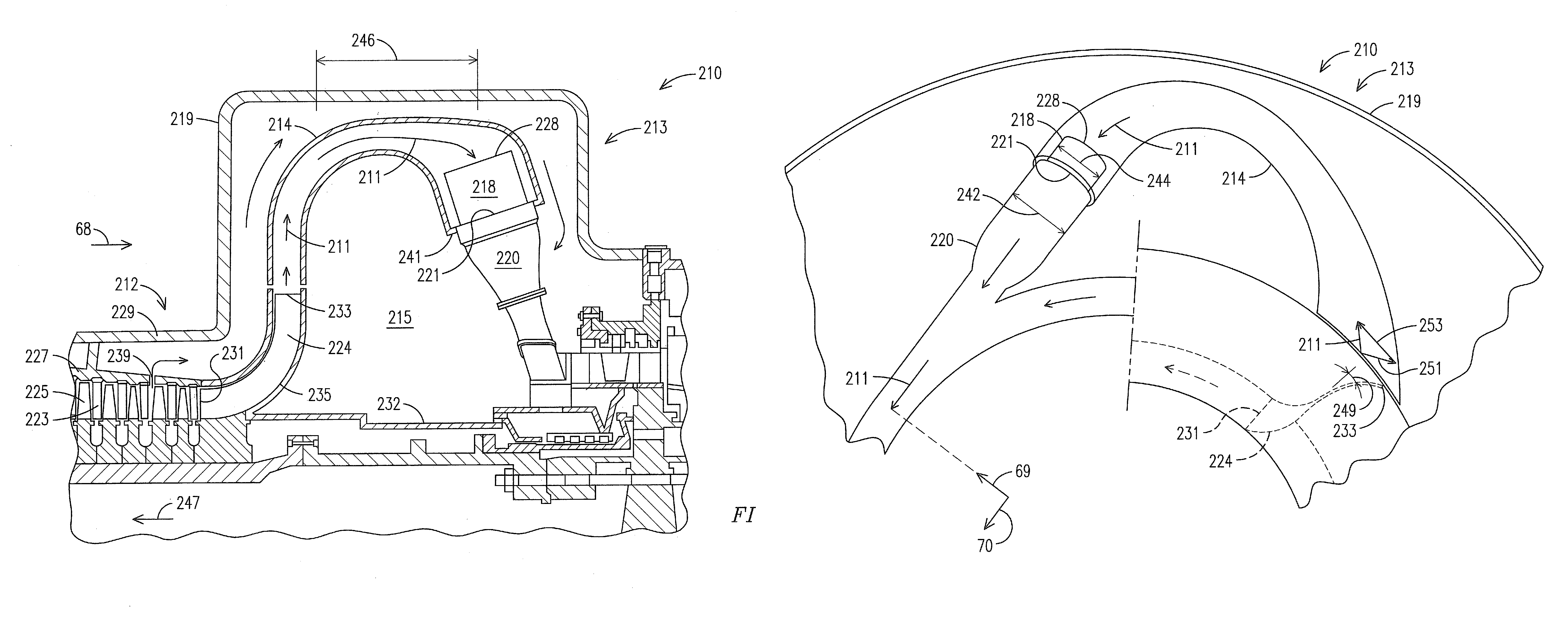
[0021]As discussed above, the inventors of the present invention recognized that an improved midframe portion of the gas turbine engine features initiating a radial air flow from the diffuser outlet. By initiating the radial air flow from the diffuser outlet, the air flow passes from the diffuser outlet to the combustor head inlet, while undergoing a reduced total angle of rotation, when compared to the air flow with the conventional midframe portion.
[0022]FIG. 4 illustrates a midframe portion 213 of a gas turbine engine 210, including a compressor section 212. Unlike the conventional compressor section 12 discussed above, the compressor section 212 includes a last stage blade 224 that directs an air flow 211 in an outward radial direction from the compressor section 212 outlet to a region and subsequently into a respective diffuser 214. The last stage blade 224 includes a leading edge 231 that is substantially aligned with the leading edges of stationary vanes 223 and rotating blad...
PUM
 Abstract
Description
Claims
Application Information