
Counter rotating axial flow fan

An axial-flow fan and counter-rotating technology, applied in the field of machinery, can solve the problems of limited influence on work efficiency and limited diffusion layer of the rotary axial-flow fan, and achieve the effects of stable operation, obvious energy saving effect and reducing efficiency loss.

Active Publication Date: 2015-05-06
燕京装备制造有限公司
View PDF5 Cites 0 Cited by
  • Summary
  • Abstract
  • Description
  • Claims
  • Application Information

AI Technical Summary

Problems solved by technology

6. Counter-rotating axial flow fans only use built-in silencers, while long-axis fans require coal mines to build special motor rooms and silencer towers
[0005] However, due to the limited diffusion layer of the above-disclosed counter-rotating axial fans, the impact on the working efficiency is limited.

Method used


Image

  • Counter rotating axial flow fan
  • Counter rotating axial flow fan
  • Counter rotating axial flow fan

Examples


Embodiment 1

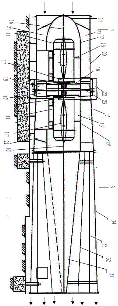
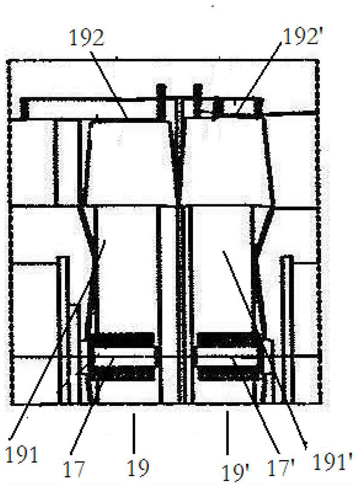
[0026] see figure 1 , The counter-rotating axial flow fan includes two sets of two-stage fans connected coaxially and a multi-layer diffuser connected to one end of the fan. From the air inlet of the fan to the end of the multi-layer diffuser, the first-stage fan 1, the second-stage fan 1' and the multi-layer diffuser 3 are sequentially included.

[0027] The first-stage fan 1 includes a first-stage motor 11 from the inside to the outside, and a first-stage explosion-proof cover 12 is arranged outside the first-stage motor 11 , and the first-stage motor 11 and the first-stage explosion-proof cover 12 are connected by a rib 13 . The first-stage explosion-proof cover 12 is semi-ellipsoidal, coaxially connected with the first-stage motor 1, the end 14 of the first-stage explosion-proof cover 12 with a small diameter faces the air inlet 15 of the first-stage blower fan 1, and the first-stage motor is installed 1 Inside the first-stage explosion-proof cover 12, there is a gap be...

Embodiment 2

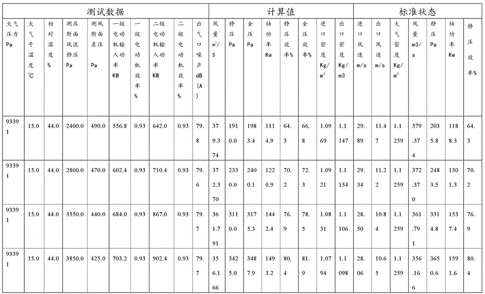
[0033] Using the counter-rotating axial flow fan of the present invention, the aerodynamic performance test is carried out, and the test results are shown in the following table: the matching motor model YBF800-10-1120, the rated power of the motor: 1120kw*2, the speed of the motor: 592r / min, two-stage operation , wind pressure test section area: 12.6923m 2 , Air volume test section area: 12.6923m 2 , Test method: on-site shutdown, short circuit test, blade installation angle: 35 。 / 30 。 (Level 1 / Level 2), fan outlet area: 32.5410m 2 , the test structure is shown in the table below:

[0034]

[0035]

[0036] It can be seen from the above table: the air volume test results are 379.4-330.2m 3 / s, the static pressure is 2035.8-5084.1Pa, the highest static pressure efficiency is 89.3%, the shaft power is 1188.3-1840.2kw, and the outlet noise is 79.1-79.9dB.


PUM


Abstract

The invention provides a counter rotating axial flow fan, which includes a motor, an impeller, an explosion-proof cover, an air duct and a single-layer or multi-layer diffuser, wherein the outlet end of the single-layer or multi-layer diffuser extends in the direction away from the air duct; and the air duct sequentially includes a core duct, a first-stage inner duct, a second-stage inner duct and a diffused outer duct from outside to inside. Due to the special structure of the air duct, the counter rotating axial flow fan has very high static efficiency.

Description

technical field [0001] The invention relates to a counter-rotating axial flow fan, which belongs to the field of machinery. Background technique [0002] At present, 85% of the fans used by major mining groups in my country are counter-rotating axial fans. Compared with traditional long-axis fans, counter-rotating fans have the following advantages. 1. Compared with the long-axis fan, the counter-rotating axial fan does not have any guide vanes, but only two impellers with opposite rotation directions; 2. The counter-rotating axial fan adopts a direct connection structure between the motor shaft and the impeller, which has high efficiency and saves energy. electrical energy. 3. The counter-rotating axial flow fan has the anti-wind performance of the motor reversal performance, and the anti-air volume can generally reach more than 65% of the positive air volume, which is extremely beneficial to mine safety. The anti-air volume of the long-axis fan is only 30-40% of the posi...

Claims


Application Information

Patent Timeline
Patent Type & Authority Patents(China)
IPC IPC(8): F04D25/08F04D29/54F04D29/32
Inventor 金恒斌
Owner 燕京装备制造有限公司
Learn More