
Composite image formed from an image sequence

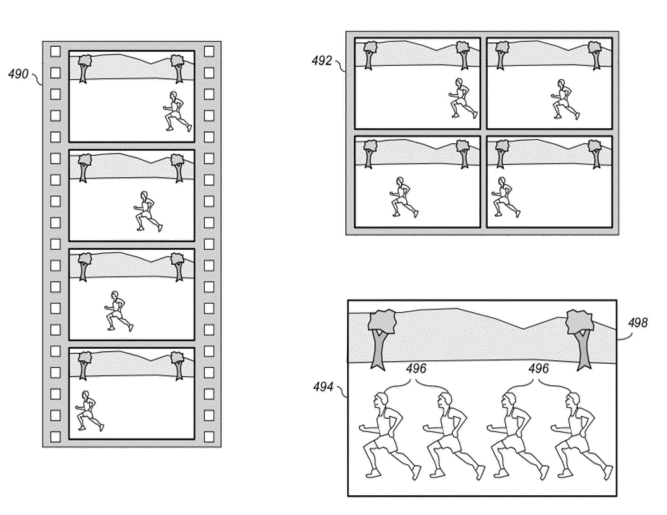
a composite image and image sequence technology, applied in the field of digital imaging, can solve the problems of increasing complexity and capabilities of digital camera devices, moving too quickly through the camera field of view, and complicated, and achieve the effect of determining the rate of motion

Inactive Publication Date: 2012-09-27
INTELLECTUAL VENTURES FUND 83 LLC
View PDF4 Cites 96 Cited by
  • Summary
  • Abstract
  • Description
  • Claims
  • Application Information

AI Technical Summary

Benefits of technology

[0015]This invention has the advantage that the frame rate used to select the subset of digital images is optimized relative to the rate of motion of the moving object.
[0016]It has the further advantage that the spatial displacement of the moving object within the composite image is optimized without the need for the user to guess at settings that would be needed to produce a desirable result.
[0017]It has the additional advantage that the rate of motion can be determined by automatically analyzing the digital images in the sequence of digital images to identify moving objects that are likely to be of interest to the user. In this way, the frame rate can be determined in a manner that accounts for the object motions that are most likely to affect perceived image quality of the composite image.

Problems solved by technology

Digital camera devices have continued to increase in complexity and capabilities with the advent of new image capture modes that offer the user unique output image characteristics.
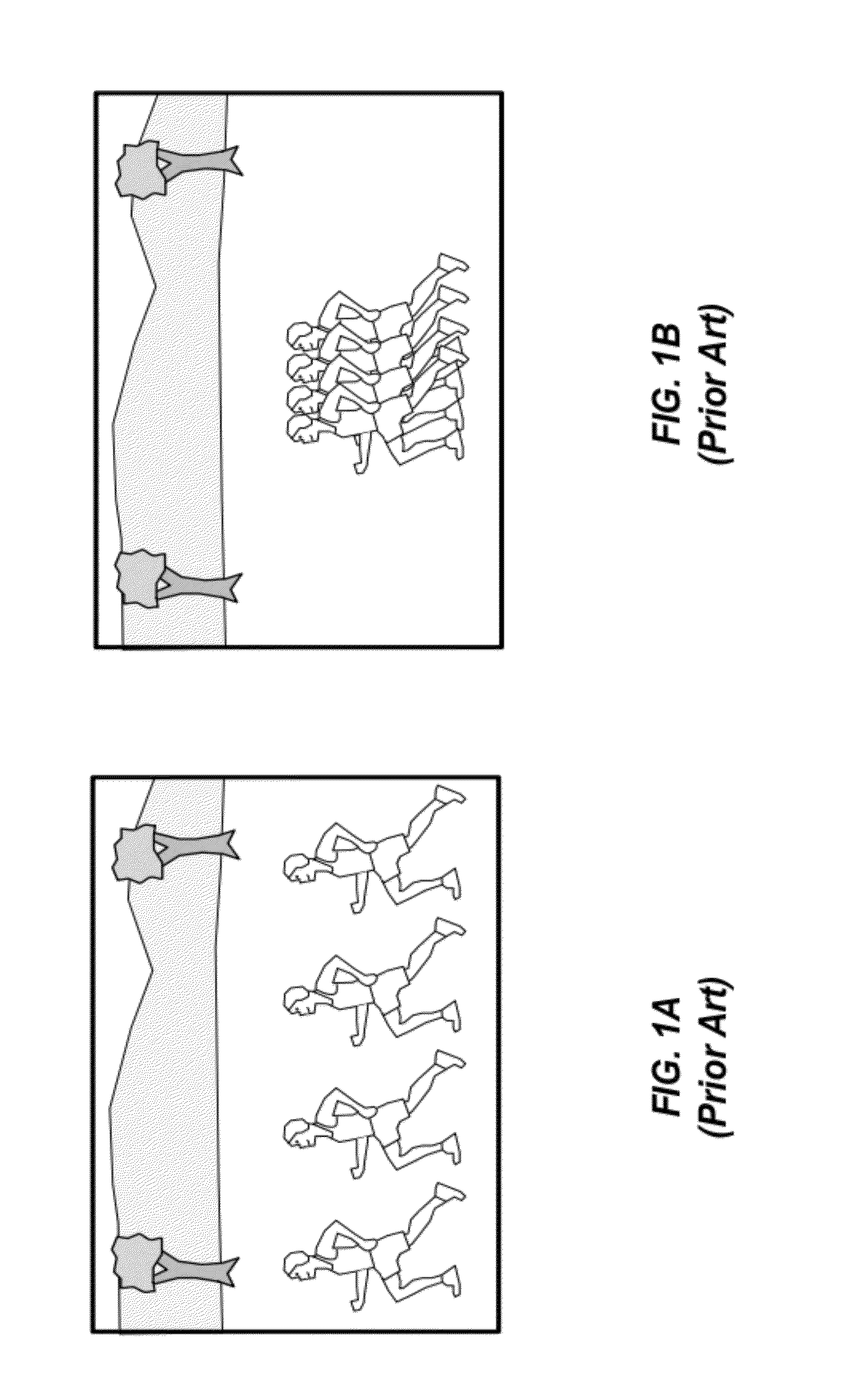
Given that knowledge about the motion of the moving objects will be rarely known in advance, this can lead to unsatisfactory results in many cases.
This can be further complicated by the fact that the user may forget to adjust the image capture settings before the capture of new conditions.
An analogous problem would occur when the subject is moving too rapidly relative to the capture rate so that it moves too quickly through the camera's field of view.
Both of these examples would result in a poor user experience of the resulting output composite image.

Method used


Image

  • Composite image formed from an image sequence
  • Composite image formed from an image sequence
  • Composite image formed from an image sequence

Examples


Embodiment Construction

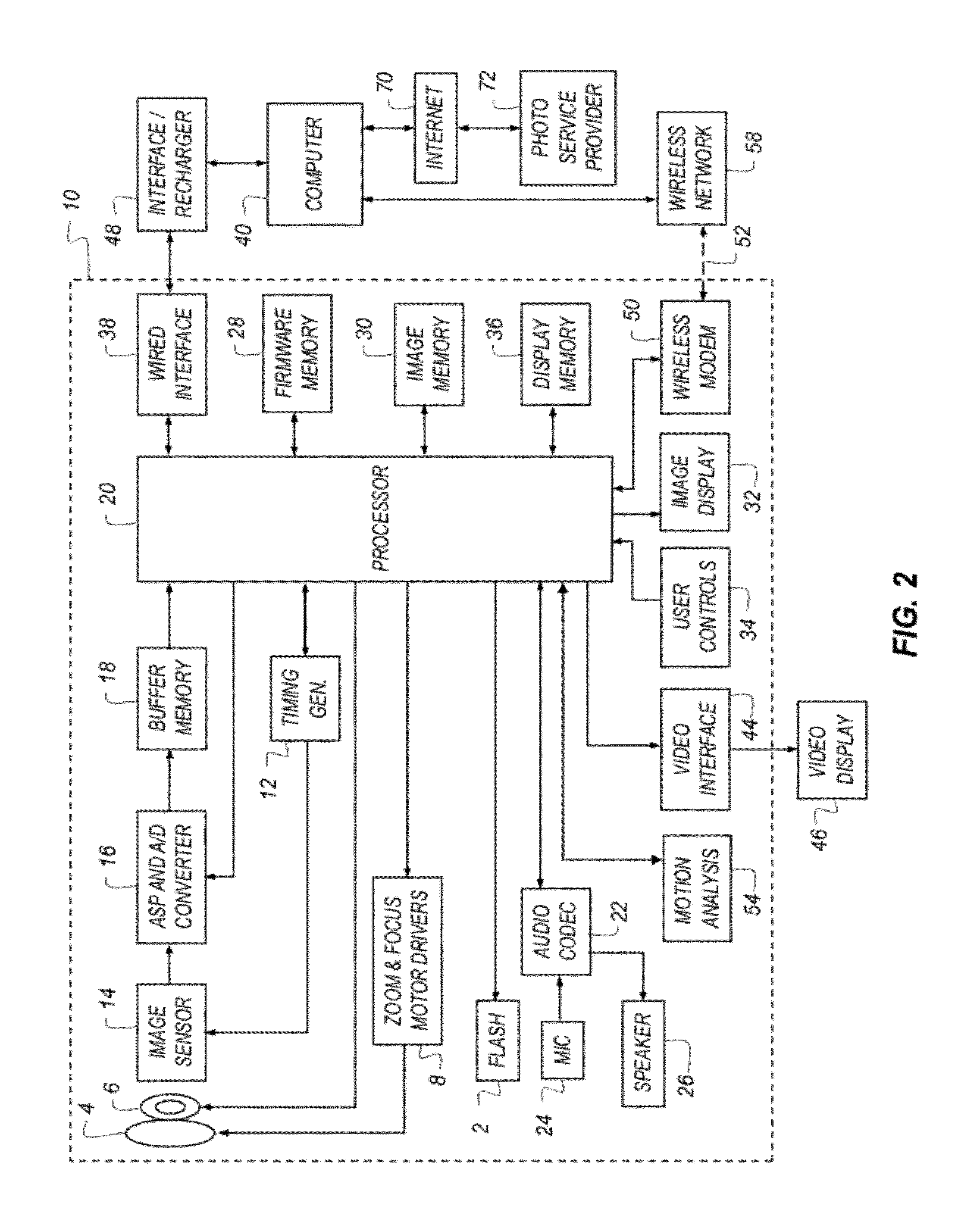
[0029]The present invention represents a digital camera having a burst image capture mode setting where the velocity of an object in the frame of view is used to determine the capture frame rate and the memory buffer requirements, which are then used to generate a composite image highlighting the object in motion. This invention provides a configuration for automatically determining various image capture settings, thereby reducing the need for the operator to manually determine the image capture settings, and reducing the number of unacceptable results.

[0030]In the following description, a preferred embodiment of the present invention will be described in terms that would ordinarily be implemented as a software program. Those skilled in the art will readily recognize that the equivalent of such software can also be constructed in hardware. Because image manipulation algorithms and systems are well known, the present description will be directed in particular to algorithms and system...


PUM


Abstract

A method for forming a composite image from a sequence of digital images, comprising: receiving a sequence of digital images of a scene, each digital image being captured at a different time, wherein the scene includes a moving object; using a data processor to automatically analyze two or more of the digital images in the sequence of digital images to determine a rate of motion for the moving object; determining a frame rate responsive to the rate of motion for the moving object; selecting a subset of the digital images from the sequence of digital images corresponding to the determined frame rate; and forming the composite image by combining the selected subset of digital images from the sequence of digital images.

Description

CROSS-REFERENCE TO RELATED APPLICATIONS[0001]Reference is made to commonly-assigned, co-pending U.S. patent application Ser. No. 13 / 021,034 (docket 96768), entitled “Estimating subject motion for capture setting determination,” by Jasinski et al.; to commonly-assigned, co-pending U.S. patent application Ser. No. 13 / 021,067 (docket K000013), entitled “Estimating subject motion between image frames,” by Jasinski et al., to commonly-assigned, co-pending U.S. patent application Ser. No. ______ (docket 96675), entitled “Digital camera having burst image capture mode,” by Fintel et al., and to commonly-assigned, co-pending U.S. patent application Ser. No. ______ (docket K000217), entitled “Digital camera for capturing an image sequence,” by Jasinski et al., each of which are incorporated herein by reference.FIELD OF THE INVENTION[0002]This invention pertains to the field of digital imaging, and more particularly to a method for adjusting a frame rate used to form a composite image from a ...

Claims


Application Information

Patent Timeline
IPC IPC(8): G06K9/36
CPCH04N5/2625H04N5/145H04N25/42
Inventor FINTEL, WILLIAM VERNONJASINSKI, DAVID WAYNE
Owner INTELLECTUAL VENTURES FUND 83 LLC
Learn More