On-duty flame stabilizer
A flame stabilizer and stabilizer technology, applied in the direction of combustion methods, lighting and heating equipment, continuous combustion chambers, etc., can solve problems such as oscillating combustion, unstable flame, and difficulty in engine ignition, so as to improve and reduce resistance, Improved spatial distribution, improved evaporation and oil-gas blending effects
- Summary
- Abstract
- Description
- Claims
- Application Information
AI Technical Summary
Problems solved by technology
Method used
Image
Examples
Embodiment 1
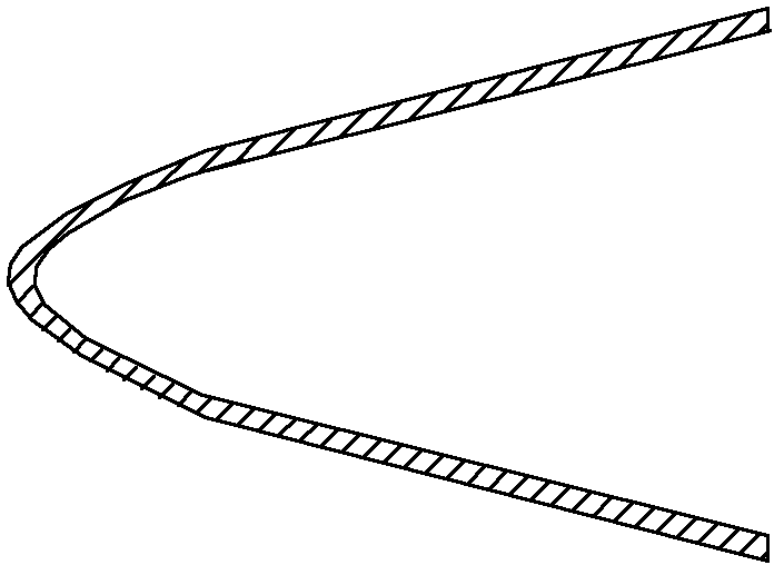
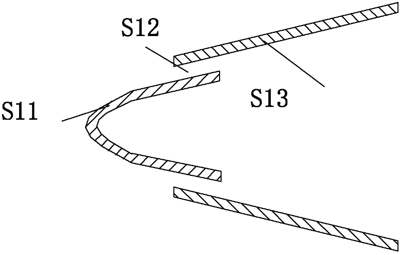
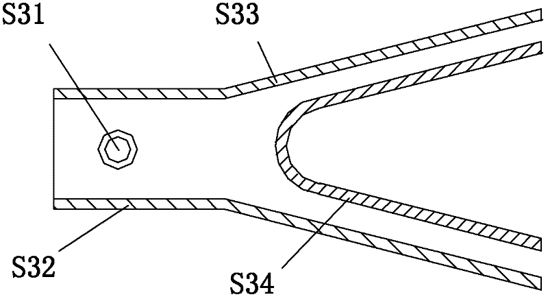
[0029] An on-duty flame stabilizer, comprising an atomization tank 1, an oil injection rod 2, an evaporation tube 3, a stabilizer side wall 4, and an air injection hole 7.
[0030] Atomization tank 1, fuel injection rod 2, and evaporation tube 3 are welded by thin steel sheets and installed on the head of the stabilizer; the top of atomization tank 1 is flush with the top of evaporation tube 3, and a certain distance downstream of atomization tank 1 is the fuel injection rod 2. Placed in the evaporation tube 3, the upstream of the spray rod 2 is the atomization tank 1, which is placed at the bottom of the evaporation tube 3; the evaporation tube 3 and the stabilizer side wall 4 are welded by thin steel sheets, and the outside of the evaporation tube 3 is the stable Device side wall 4.
[0031]In the present invention, the atomization tank 1, fuel injection rod 2, and evaporation tube 3 are welded with thin steel sheets to ensure that the distance between the two sides of the a...
Embodiment 2
[0033] An on-duty flame stabilizer, comprising an atomization tank 1, an oil injection rod 2, an evaporation tube 3, a stabilizer side wall 4, and an air injection hole 7.
[0034] Atomization tank 1, fuel injection rod 2, and evaporation tube 3 are welded by thin steel sheets and installed on the head of the stabilizer; the top of atomization tank 1 is flush with the top of evaporation tube 3, and a certain distance downstream of atomization tank 1 is the fuel injection rod 2. Placed in the evaporation tube 3, the upstream of the spray rod 2 is the atomization tank 1, which is placed at the bottom of the evaporation tube 3; the flange of the evaporation tube 3 and the side wall of the stabilizer 4 is welded, and the outside of the evaporation tube 3 is the stabilizer side wall 4.
[0035] In the present invention, the atomization tank 1, fuel injection rod 2, and evaporation tube 3 are welded with thin steel sheets to ensure that the distance between the two sides of the atom...
PUM
 Abstract
Description
Claims
Application Information
 - R&D
- Intellectual Property
- Life Sciences
- Materials
- Tech Scout
- Unparalleled Data Quality
- Higher Quality Content
- 60% Fewer Hallucinations
Browse by: Latest US Patents, China's latest patents, Technical Efficacy Thesaurus, Application Domain, Technology Topic, Popular Technical Reports.
© 2025 PatSnap. All rights reserved.Legal|Privacy policy|Modern Slavery Act Transparency Statement|Sitemap|About US| Contact US: help@patsnap.com


