
Gas sensor

Active Publication Date: 2012-10-04
NGK INSULATORS LTD
View PDF2 Cites 11 Cited by
  • Summary
  • Abstract
  • Description
  • Claims
  • Application Information

AI Technical Summary

Benefits of technology

[0017]In the gas sensor according to the present invention, the heater may be formed at a position away from the reference electrode with the other solid electrolyte layer interposed therebetween. In this case, the other solid electrolyte layer contacts the surface of the one solid electrolyte layer on the reference electrode side, and the one solid electrolyte layer is a layer on which the reference electrode is formed directly thereon. Thus, compared to a case in which two or more solid electrolyte layers are arranged between the reference electrode and the heater, the distance between the heater and the reference electrode and the distance between the heater and the measurement electrode are decreased, thereby suppressing occurrence of a situation that causes the temperature difference between the reference electrode and the measurement electrode. The gas sensor according to the present invention may include a heater insulation layer formed of a porous body, is formed between the heater and at least one of the solid electrolyte layers disposed adjacent to the heater, and insulates the heater from

Problems solved by technology

The above-described related-art gas sensor has a problem in that variation of the electromotive force is increased due to the temperature differ

Method used


Image

  • Gas sensor
  • Gas sensor
  • Gas sensor

Examples


Example

First Example and First Comparative Example

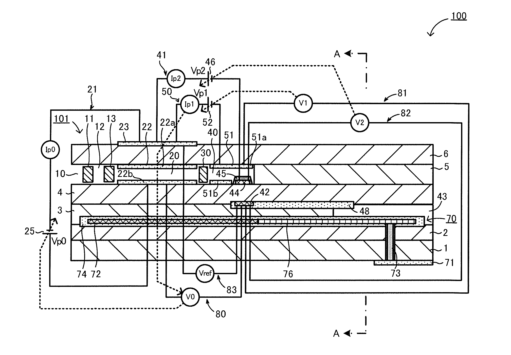
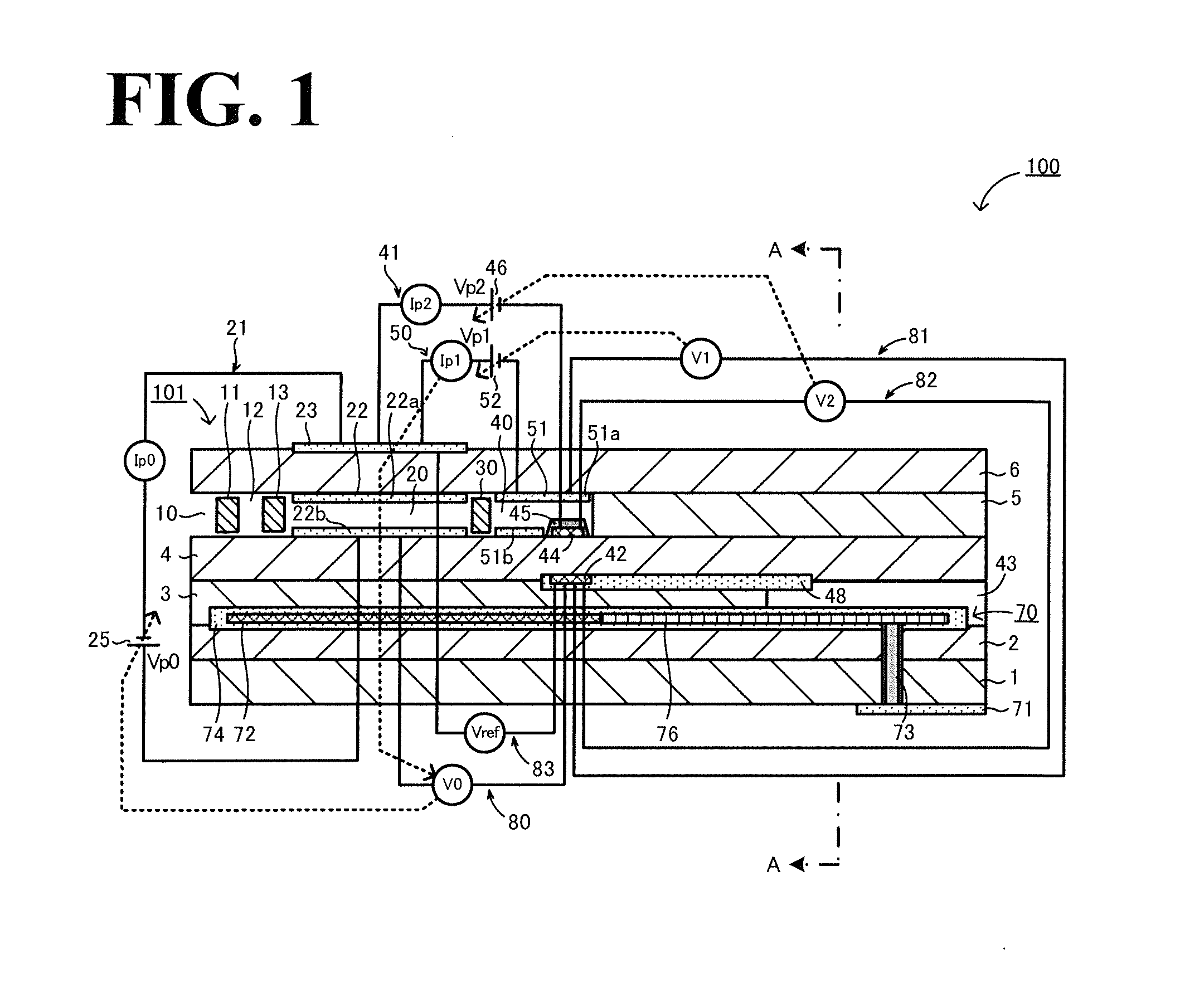
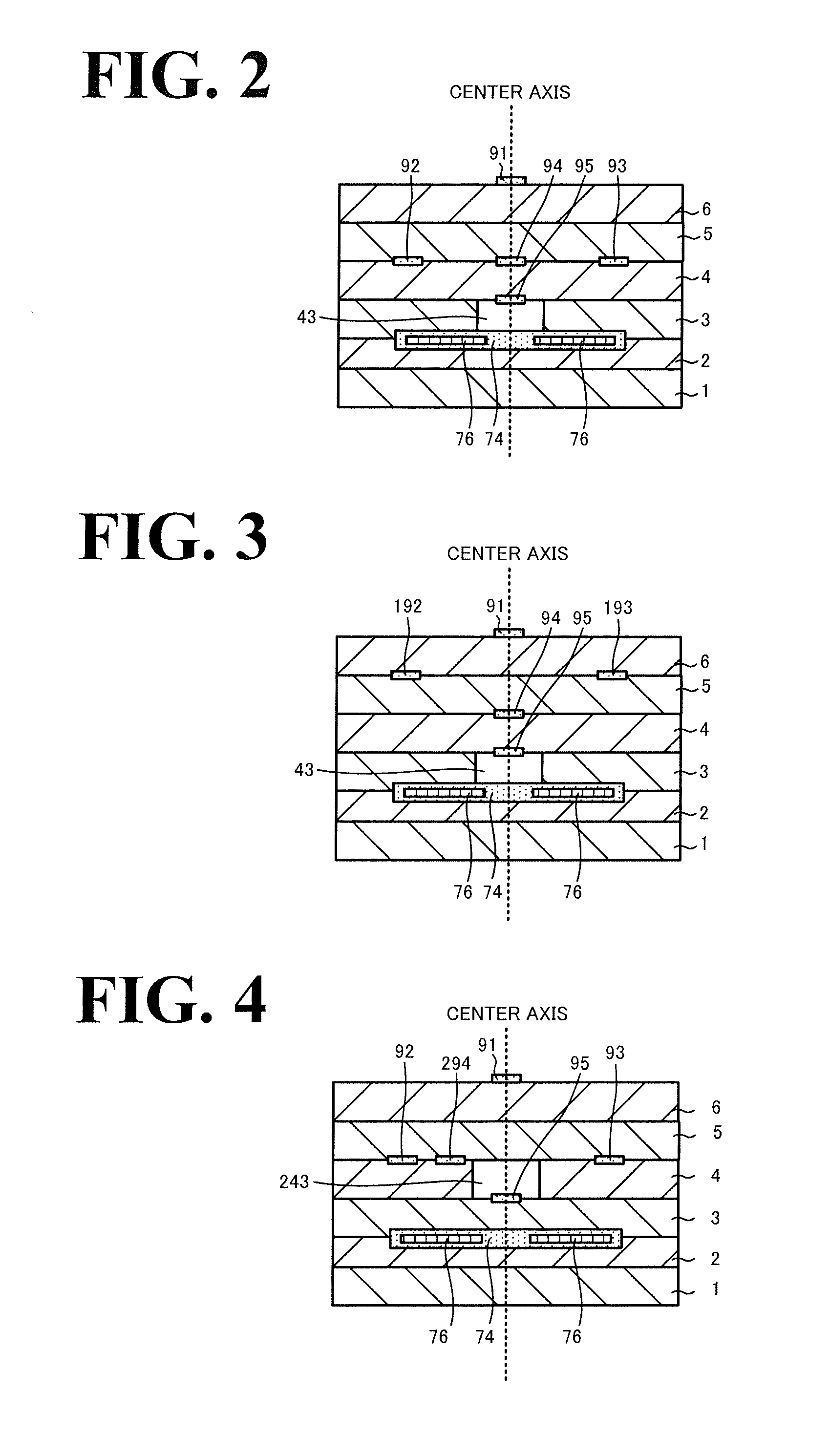
[0077]As a first example, 15 sensor elements 101 illustrated in FIGS. 1 and 2 are produced using the above-described production method. As a first comparative example, 15 sensor elements each similar to a sensor element 307 illustrated in FIG. 6 are produced. That is, each of these sensor elements has the structure similar to that of the first example except that a reference electrode and a measurement electrode are formed on different solid electrolyte layers, not only the solid electrolyte layer but also a reference gas introduction space are disposed between the reference electrode and the measurement electrode, the reference gas introduction space is formed in a first solid electrolyte layer, and a pressure releasing hole and the reference gas introduction space are separately formed. In the first comparative example, leads are arranged differently from those in the first example. FIG. 4 illustrates the arrangement of the leads of the f...

Example

[0078]The sensor elements of the first example and the first comparative example were maintained at a normal operating temperature (800° C.) in the atmosphere using the heater. An electromotive force between the reference electrode and the measurement electrode was measured. The measurement was performed on five sensor elements of each of the first example and the first comparative example. The range of variation (difference between the maximum and the minimum electromotive forces) of each of five measured electromotive forces was calculated. The results were 7 mV for the sensor elements of the first example, and 14 mV for the sensor elements of the first comparative example.

[0079]As a result, it was found that, for the sensor elements of the first example, variation in the electromotive force was decreased because a situation that caused the temperature difference between the reference electrode 42 and the measurement electrode 44 due to heat from the heater 72 was suppressed. This...


PUM


Abstract

A gas sensor is provided with a multilayer body of solid electrolyte layers, a measurement electrode, a reference electrode, a reference gas introduction layer, a detection unit and a heater. The reference electrode and the measurement electrode are formed directly on the same first solid electrolyte layer. Thus, heat from the heater is transferred from a third substrate layer to the first solid electrolyte layer, and also to the reference electrode and the measurement electrode through the same first solid electrolyte layer. The reference electrode is covered with a reference gas introduction layer, formed of a porous body. The transference of heat from the heater to the reference electrode through the reference gas introduction layer is smaller than the transference of heat from the heater to the reference electrode through the first solid electrolyte layer on which the reference electrode is formed directly.

Description

BACKGROUND OF THE INVENTION[0001]1. Field of the Invention[0002]The present invention relates to gas sensors.[0003]2. Description of the Related Art[0004]To date, a gas sensor that detects the concentration of a specified gas such as NOx included in an object gas such as an exhaust gas from an automobile has been known. For example, Patent Literature 1 discloses a gas sensor including a long plate-shaped sensor element formed of a plurality of gas-tight oxygen ion conductive solid electrolyte layers stacked one on top of one another. In this sensor element, a measurement electrode and a reference electrode are formed on separate solid electrolyte layers. An object gas is introduced on the measurement electrode side and a reference gas is introduced on the reference electrode side, and the concentration of a specified gas in the object gas is detected in accordance with an electromotive force generated between the reference electrode and the measurement electrode.[0005]FIG. 6 is a sc...

Claims


Application Information

Patent Timeline
IPC IPC(8): G01N27/407
CPCG01N27/4067
Inventor MURAKAMI, MIKASAITO, NAOYASEIMORI, TOMOYA
Owner NGK INSULATORS LTD
Learn More