
Monitoring apparatus and method

a technology of monitoring apparatus and monitoring method, applied in the direction of process and machine control, using reradiation, instruments, etc., can solve the problems of unnecessarily triggering the application of brakes, apparatus failing to recognise the alignment change, and causing the risk of collision of the host vehicle. , to achieve the effect of reducing the risk of collision of the host vehicl

Active Publication Date: 2012-10-04
JAGUAR LAND ROVER LTD
View PDF11 Cites 23 Cited by
  • Summary
  • Abstract
  • Description
  • Claims
  • Application Information

AI Technical Summary

Benefits of technology

[0005]In one aspect of the invention for which protection is sought there is provided monitoring apparatus for monitoring one or more target objects in an environment external to a host vehicle by means of at least one sensor, the apparatus being arranged to trigger at least one action responsive to the speed of the host vehicle and detection of predetermined relative movement between the host vehicle and the one or more target objects thereby to reduce a risk of collision of the host vehicle with the one or more target objects, the apparatus being further arranged to determine whether the at least one sensor is correctly aligned with respect to the host vehicle, wherein when the monitoring apparatus commences monitoring of the environment the apparatus is arranged not to trigger the at least one action until it is determined that the at least one sensor is correctly aligned.

Problems solved by technology

When the monitoring apparatus commences monitoring of the environment as the vehicle subsequently drives away, the risk exists that the apparatus will fail to recognise that a change in alignment has occurred before triggering automatically an action such as application of the brakes of the vehicle.
Thus the apparatus may determine that a target object presents a collision risk when in fact it does not, triggering application of the brakes unnecessarily.

Method used


Image

  • Monitoring apparatus and method
  • Monitoring apparatus and method
  • Monitoring apparatus and method

Examples


Embodiment Construction

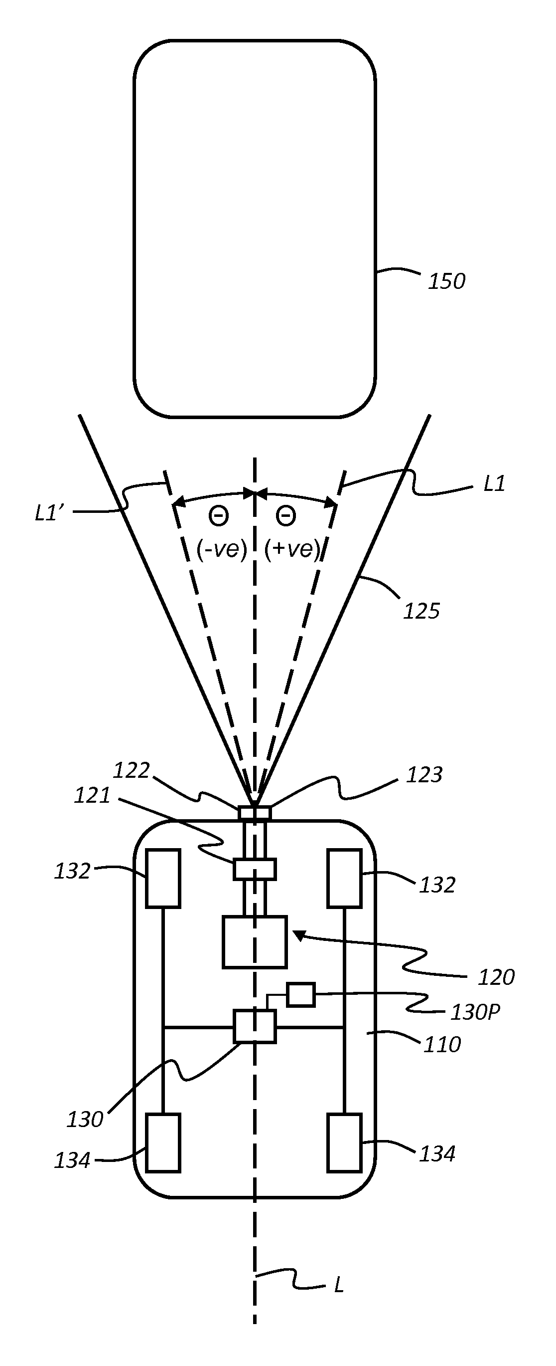
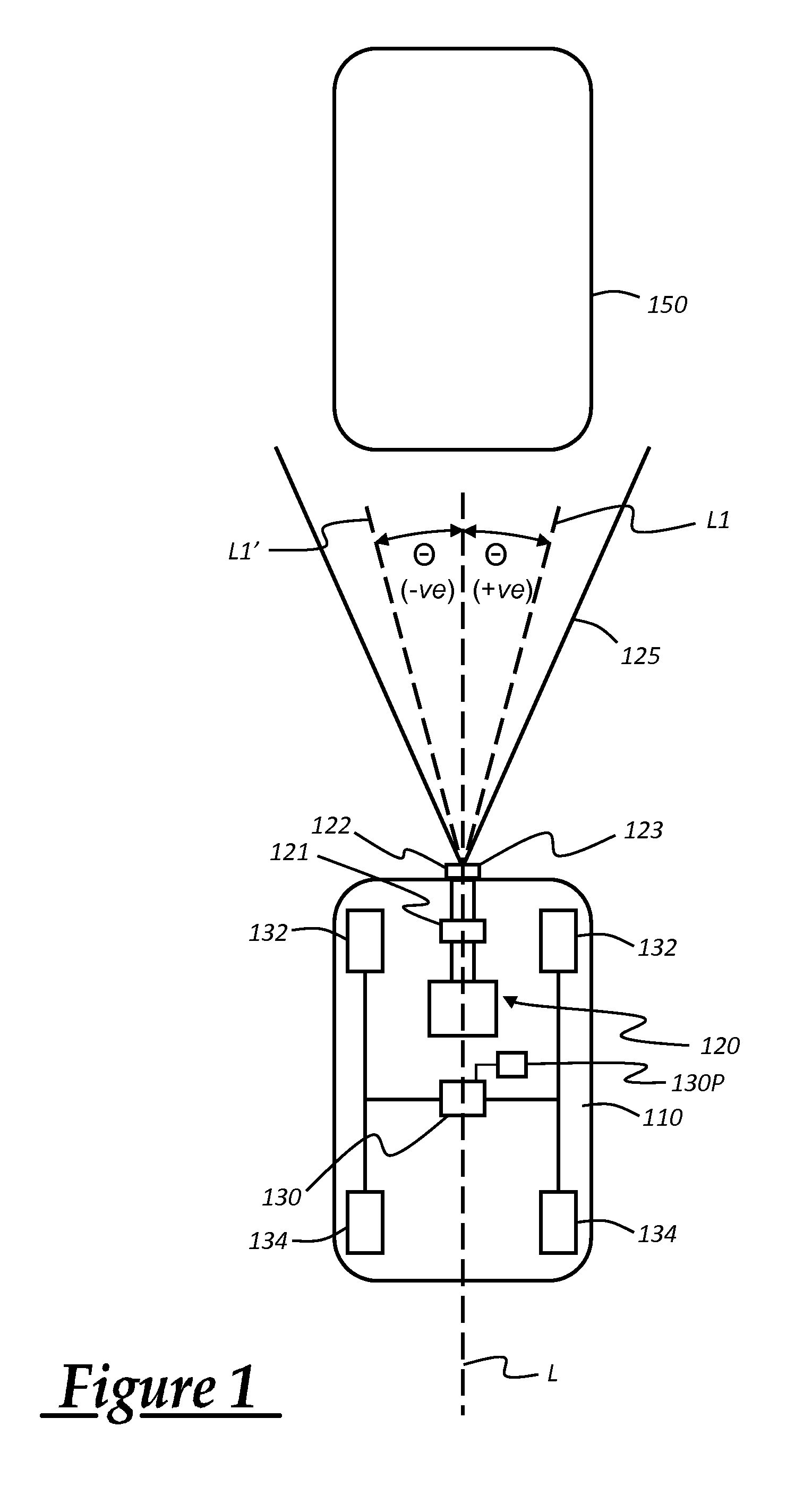
[0046]In one embodiment of the invention a monitoring apparatus 120 is provided in a motor vehicle 110 as shown in FIG. 1. The monitoring apparatus 120 has a radar module 121 arranged to identify the presence of a target object ahead of the vehicle 110 such as a lorry 150. The radar module 121 is arranged to determine the range R of the object from the vehicle 110 and the rate of change of the range of the object R′ from the vehicle 110 (‘range rate’).

[0047]The monitoring apparatus 120 is part of an intelligent emergency braking system (IEB) of the vehicle 100. The IEB system is operable to control a braking system of the vehicle 110 to slow or stop the vehicle in the event that certain prescribed conditions are met. The apparatus 120 is therefore coupled to a brake controller 130 of the vehicle. The brake controller 130 is in turn arranged to control a braking system of the vehicle responsive to an input from the apparatus 120 or a driver-operated brake pedal 130P.

[0048]The braking...


PUM


Abstract

An apparatus for monitoring one or more target objects in an environment external to a host vehicle by means of at least one sensor, the apparatus being arranged to trigger at least one action responsive to the detection of prescribed relative movement between the host vehicle and the one or more target objects. The apparatus is arranged to determine whether the at least one sensor is correctly aligned with respect to the host vehicle whereby, when the apparatus commences monitoring of the environment, the apparatus is arranged not to trigger the at least one action until the apparatus has determined that the at least one sensor is correctly aligned.

Description

FIELD OF THE INVENTION[0001]The present invention relates to an apparatus and a method for monitoring a target object external to a vehicle. Aspects of the invention relate to an apparatus, to a method and to a vehicle.BACKGROUND[0002]It is known to provide a vehicle having apparatus arranged to identify target objects in front of or behind the vehicle and to activate automatically a braking system of the vehicle if the vehicle determines that collision with the object is imminent.[0003]Such systems typically employ radar or ultrasonic transmitter / receiver modules. The well known Doppler effect is used to determine a range and rate of change of range (or ‘range rate’) of the object from the vehicle.[0004]It is desirable to provide improved apparatus to increase the likelihood that the apparatus will correctly identify a target object that represents a collision risk to the vehicle. It is an aim of the present invention to address this issue. Other aims and advantages of the inventio...

Claims


Application Information

Patent Timeline
Patent Type & Authority Applications(United States)
IPC IPC(8): G06F7/00G01S13/931
CPCG01S7/4026G01S13/584G01S13/931G01S2013/9364G01S2007/403G01S2013/9346G01S2013/9353G01S2007/4091G01S2013/93185G01S2013/9324G01S2013/932G01S7/403G01S7/4091B60W30/09
Inventor CUND, MARKWIDDOWSON, PAULDUNOYER, ALAINBREUGELMANS, ADRIE
Owner JAGUAR LAND ROVER LTD
Learn More