
Ballistic protection grid having an access hatch

Active Publication Date: 2012-10-11
NEXTER SYST SA
View PDF15 Cites 7 Cited by
  • Summary
  • Abstract
  • Description
  • Claims
  • Application Information

AI Technical Summary

Benefits of technology

[0015]According to one embodiment, the locking means comprises at least a first tab on one side of the hatch and positioning itself facing a second tab secured to an edge of the grid, a fastenin

Problems solved by technology

On the armored vehicles, the grids constitute an obstacle to the access to the elements disposed at the periphery of the vehicle.
However, this access solution through the grid has one drawback.
At the joint between the opening and the hatch, the juxtaposition of the frames significantly increases the apparent surface exposed to the threat, and the probability of having this junction region impacted by a projectile rocket.

Method used


Image

  • Ballistic protection grid having an access hatch
  • Ballistic protection grid having an access hatch
  • Ballistic protection grid having an access hatch

Examples


Embodiment Construction

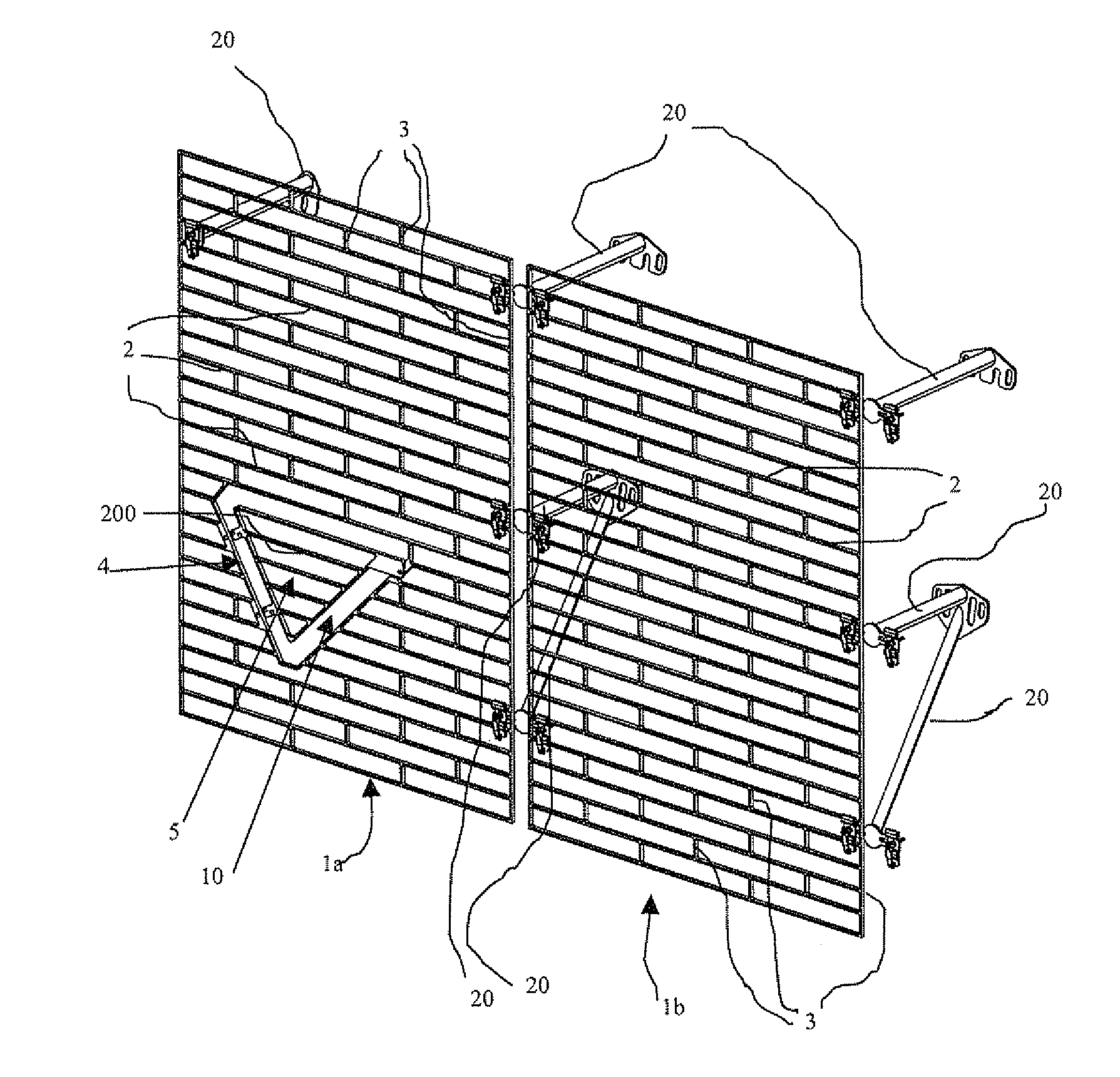
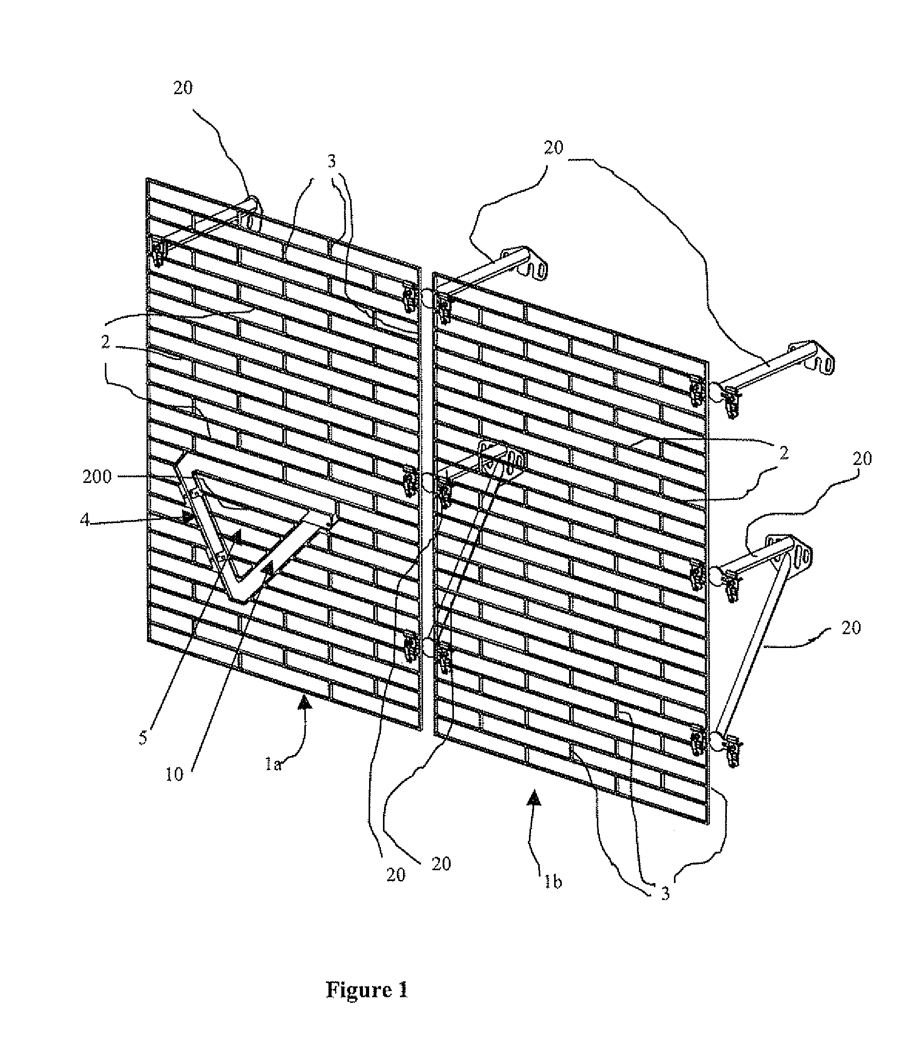
[0022]According to FIG. 1, ballistic protection grids 1a and 1b are placed at a distance from the walls of a vehicle using arms 20 (the walls and the vehicle are not shown). These grids 1a and 1b comprise bars 2 parallel to each other. These bars 2 are connected to each other by posts 3.

[0023]The grid 1a according to the invention comprises an opening 4 partially concealed by a hatch 5. The hatch 5 is secured to the grid 1a and it comprises bars 200. The hatch 5 and the grid 1a are made of the same material, preferably steel of a hardness greater than 360 Brinells, and the bars 2 and 200 have the same dimensional features for the hatch 5 and for the grid 1a.

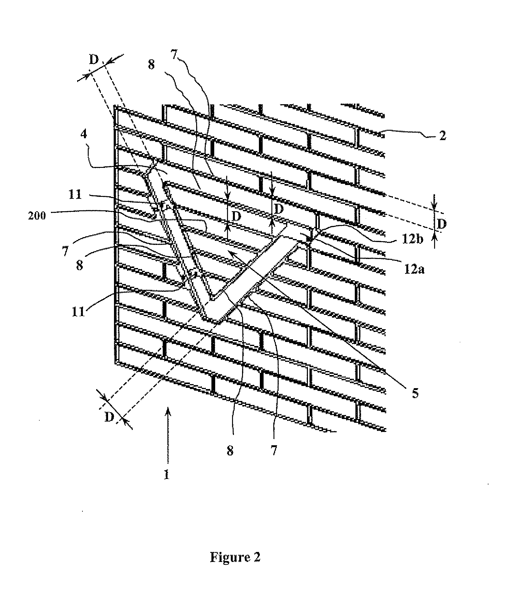
[0024]According to FIG. 2, each bar 2 of the grid is separated from the neighboring bar by a distance D. This inter-bar distance D is sufficiently reduced to prevent a projectile (projectile not shown) from passing between the bars 2 without its warhead coming to hit at least one bar 2. This distance D is also chosen sufficientl...


PUM


Abstract

The subject-matter of the invention is a ballistic protection grid for a vehicle comprising an access hatch received in an opening of the grid, wherein the grid and the hatch comprise bars separated from each other by an inter-bar distance, the protection grid being characterized in that the access hatch partially conceals the opening of the grid, each edge of the opening of the grid being separated from the sides of the hatch by a distance substantially equal to the inter-bar distance.

Description

CROSS REFERENCE TO RELATED APPLICATIONS[0001]Applicant claims priority under 35 U.S.C. 119 of French patent application no. 1101095 filed on Jul. 4, 2011.STATEMENT REGARDING FEDERALLY SPONSORED RESEARCH OR DEVELOPMENT[0002]Not ApplicableTHE NAMES OF THE PARTIES TO A JOINT RESEARCH AGREEMENT[0003]Not ApplicableINCORPORATION-BY-REFERENCE OF MATERIAL SUBMITTED ON A COMPACT DISC[0004]Not ApplicableBACKGROUND OF THE INVENTION[0005]The invention belongs to the technical field of ballistic protection grids.[0006]To protect the armored vehicles from the attacks of shaped charge projectiles, rigid protection grids placed at a distance from the walls of the vehicle are used.[0007]These grids comprise bars spaced from each other. The function of the bars is to deteriorate the warhead of the incident projectile, so as to destroy the firing contact of the shaped charge, thus preventing its triggering.[0008]The bars of the grid should not be too spaced apart from each other to prevent the passage...

Claims


Application Information

Patent Timeline
IPC IPC(8): F41H7/02
CPCF41H5/023F41H5/026F41H5/06F41H7/04F41H5/226
Inventor HUBSCH, ALAIN
Owner NEXTER SYST SA
Learn More