Antenna device and method of setting resonant frequency of antenna device

a technology of antenna device and resonant frequency, which is applied in the direction of loop antenna with ferromagnetic core, waveguide type device, instrument, etc., can solve the problems of ineffectively increasing the communication range of metal layer 30/b>, not regularly or reliably obtaining substantial effect, etc., to achieve the maximum possible communication range and stable communication

Inactive Publication Date: 2012-10-18
MURATA MFG CO LTD
View PDF6 Cites 49 Cited by
  • Summary
  • Abstract
  • Description
  • Claims
  • Application Information

AI Technical Summary

Benefits of technology

[0009]Accordingly, preferred embodiments of the present invention provide an antenna device that, even when the size of the antenna device is small compared to that of an antenna on the communication-partner side, is capable of stable communication and is also capable of increasing the maximum possible communication range, and also provide a method of adjusting the central resonant frequency of the antenna device.
[0012]According to various preferred embodiments of the present invention, a current flows through the conductor layer so that a magnetic field, which is generated by the current flowing through the coil conductor, is blocked. Then, a current flows around the periphery of the opening in the conductor layer and a current flows along the periphery of the slit and around the periphery of the conductor layer due to the cut-edge effect. As a result, a magnetic field arises around the conductor layer and the communication range can be increased.

Problems solved by technology

Therefore, a substantial effect cannot be regularly or reliably obtained by changing the positions of shielding members such as the battery pack 25.
Furthermore, the metal layer 30 effectively does not regularly or reliably increase the communication range in a state in which the antenna device and the antenna on the communication partner side are spaced apart from each other.

Method used


Image

  • Antenna device and method of setting resonant frequency of antenna device
  • Antenna device and method of setting resonant frequency of antenna device
  • Antenna device and method of setting resonant frequency of antenna device

Examples


first preferred embodiment

[0023]An antenna device and a method of setting a resonant frequency of the antenna device according to a first preferred embodiment of the present invention will be described with reference to FIGS. 2A to 4B.

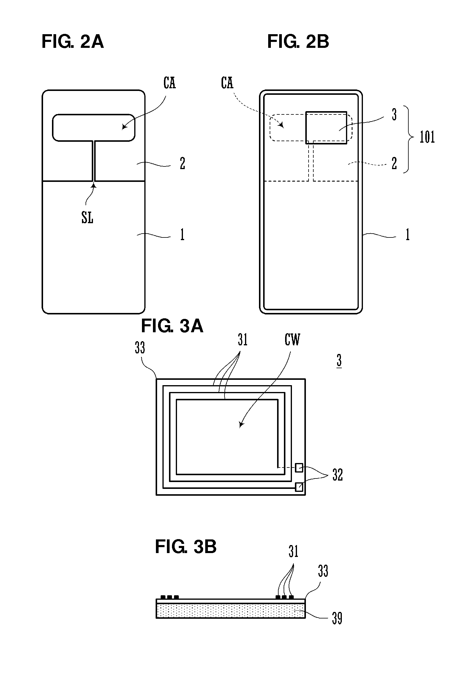
[0024]FIG. 2A is a view of a rear surface of an electronic appliance that is equipped with the antenna device according to the first preferred embodiment of the present invention. The rear surface of the electronic appliance faces an antenna on a reader / writer side, which is a communication partner side. FIG. 2B is a plan view of the interior of a lower casing on the rear surface side. Only the structures of principal components are illustrated in FIGS. 2A and 2B.

[0025]As illustrated in FIG. 2A, a conductor layer 2 is located on an outer surface of a lower casing 1. The conductor layer 2 is, for example, a vapor-deposited metal film such as an aluminum film. A conductor opening CA and a slit SL, which connects the conductor opening CA and an outer edge of the conductor layer 2,...

second preferred embodiment

[0051]FIGS. 5A and 5B are views of an antenna device 102 according to a second preferred embodiment of the present invention. FIG. 5A is a plan view from the inner surface side of the lower casing 1 of the electronic appliance. Furthermore, FIG. 5B is a plan view of a state in which the antenna coil module 3 has been mounted on an inner surface of the lower casing 1.

[0052]In the second preferred embodiment, the conductor layer 2 is preferably provided on an inner surface of the lower casing 1. The conductor layer 2 is preferably formed by vapor deposition of a metal film such as aluminum or by adhesion of a metal foil, for example. In this way, a conductor layer may be provided on an inner surface of the casing.

[0053]Moreover, in the preferred embodiment illustrated in FIGS. 5A and 5B, the slit SL of the conductor layer 2 is provided in a portion for which the distance from the conductor opening CA to the edge is short.

[0054]The conductor layer 2 may be connected to the ground of a ...

third preferred embodiment

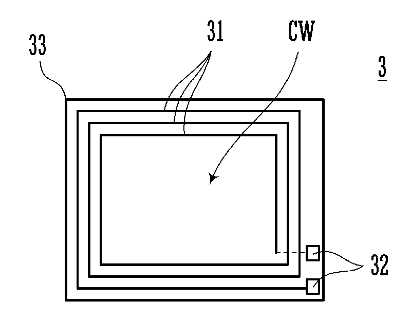
[0055]FIGS. 6A and 6B are plan views of an antenna device 103 according to a third preferred embodiment of the present invention. FIG. 6A illustrates an electric current that flows through the coil conductor 31 and FIG. 6B illustrates an electric current 1 that flows through the conductor layer 2. The antenna device 103 preferably includes the antenna coil module 3 and the conductor layer 2. The antenna coil module 3 is preferably constructed by stacking the flexible substrate on which the spiral-shaped coil conductor 31 has been formed on top of a magnetic sheet. Basically, this is the same as the configuration illustrated in FIGS. 3A and 3B. However, in this preferred embodiment, the two terminals of the coil conductor extend from the flexible substrate and connectors are provided at positions separated from the coil conductor 31.

[0056]The conductor layer 2 preferably includes the conductor opening CA and the slit SL, which connects the conductor opening CA and the outer edge of t...


PUM

PropertyMeasurementUnit
currentaaaaaaaaaa
resonant frequencyaaaaaaaaaa
sizeaaaaaaaaaa

Abstract

In antenna device, a coil conductor of an antenna coil module and a conductor layer at least partially overlap. A current flows in the conductor layer and blocks a magnetic field generated by a current flowing in the coil conductor. A current, which flows around the periphery of an opening of the conductor layer, flows along the periphery of a slit and around the periphery of the conductor layer due to a cut-edge effect. Since magnetic flux does not pass through the conductor layer, magnetic flux attempts to bypass the conductor layer along a path in which the conductor opening of the conductor layer is on the inside and the outer edge of the conductor layer is on the outside. Accordingly, the magnetic flux generates relatively large loops linking the inside and the outside of a coil conductor of an antenna on a reader / writer side.

Description

BACKGROUND OF THE INVENTION[0001]1. Field of the Invention[0002]The present invention relates to antenna devices preferably for use in RFID systems and short-range wireless communication systems, such systems performing communication through electromagnetic signals with appliances that are communication partners, and also relates to methods of setting the resonant frequency of such antenna devices.[0003]2. Description of the Related Art[0004]In RFID systems and short-range wireless communication systems, which have become widely used in recent years, in order to facilitate communication between mobile electronic appliances such as mobile telephones or between a mobile electronic appliance and a reader / writer, a communication antenna is mounted in each of the appliances. Among such antennas, an antenna to be mounted in a mobile electronic appliance is disclosed in Japanese Unexamined Patent Application Publication No. 2006-270681.[0005]FIG. 1 is a view illustrating communication betw...

Claims


Application Information

Patent Timeline
Patent Type & Authority Applications(United States)
IPC IPC(8): H01Q1/36H01Q7/00H01P11/00H01Q7/06
CPCH01Q1/38Y10T29/49016H01Q7/04H04B5/0081H01Q1/2225H01Q1/48H01Q1/52H01Q19/062H01P11/001H01Q1/22H01Q1/36H01Q7/06H01P11/00H01Q19/02G06K19/07779H01Q7/00H01Q1/526H01Q1/243H01Q1/2216H01Q1/2291
Inventor KATO, NOBORUTANIGUCHI, KATSUMISASAKI, JUNGOCHI, NAOKI
Owner MURATA MFG CO LTD
Why Eureka
Try Eureka