Diversity receiver and diversity reception method

a receiver and diversity technology, applied in diversity/multi-antenna systems, polarisation/directional diversity, amplitude demodulation, etc., can solve the problems of inability to perform conventional structures, inability to compare power, and significant degradation of reception performance, etc., to achieve stable communication

Inactive Publication Date: 2006-06-22
PANASONIC CORP
View PDF4 Cites 34 Cited by
  • Summary
  • Abstract
  • Description
  • Claims
  • Application Information

AI Technical Summary

Benefits of technology

[0029] According to the present invention, an optimum antenna can be selected within a short period of time. Since an optimum antenna can be selected for every one of arriving packets, stable communication can be realized even when the transmission environment abruptly changes or even when packets are transmitted from a plurality of terminals.

Problems solved by technology

In mobile communication, such as wireless LAN (Local Area Network), or the like, the reception performance has been known to significantly deteriorate due to a fading phenomenon, i.e., a tremendous variation in received field intensity which is caused by reflected and / or scattered waves.
However, in the receiver as shown in FIG. 17, the received power cannot be precisely determined without convergence of a feedback loop formed by the AGC circuit 924 and the control voltage generator 934, and accordingly, comparison of power consumes time.
Thus, these processes cannot be performed in the conventional structure.

Method used


Image

  • Diversity receiver and diversity reception method
  • Diversity receiver and diversity reception method
  • Diversity receiver and diversity reception method

Examples


embodiment 1

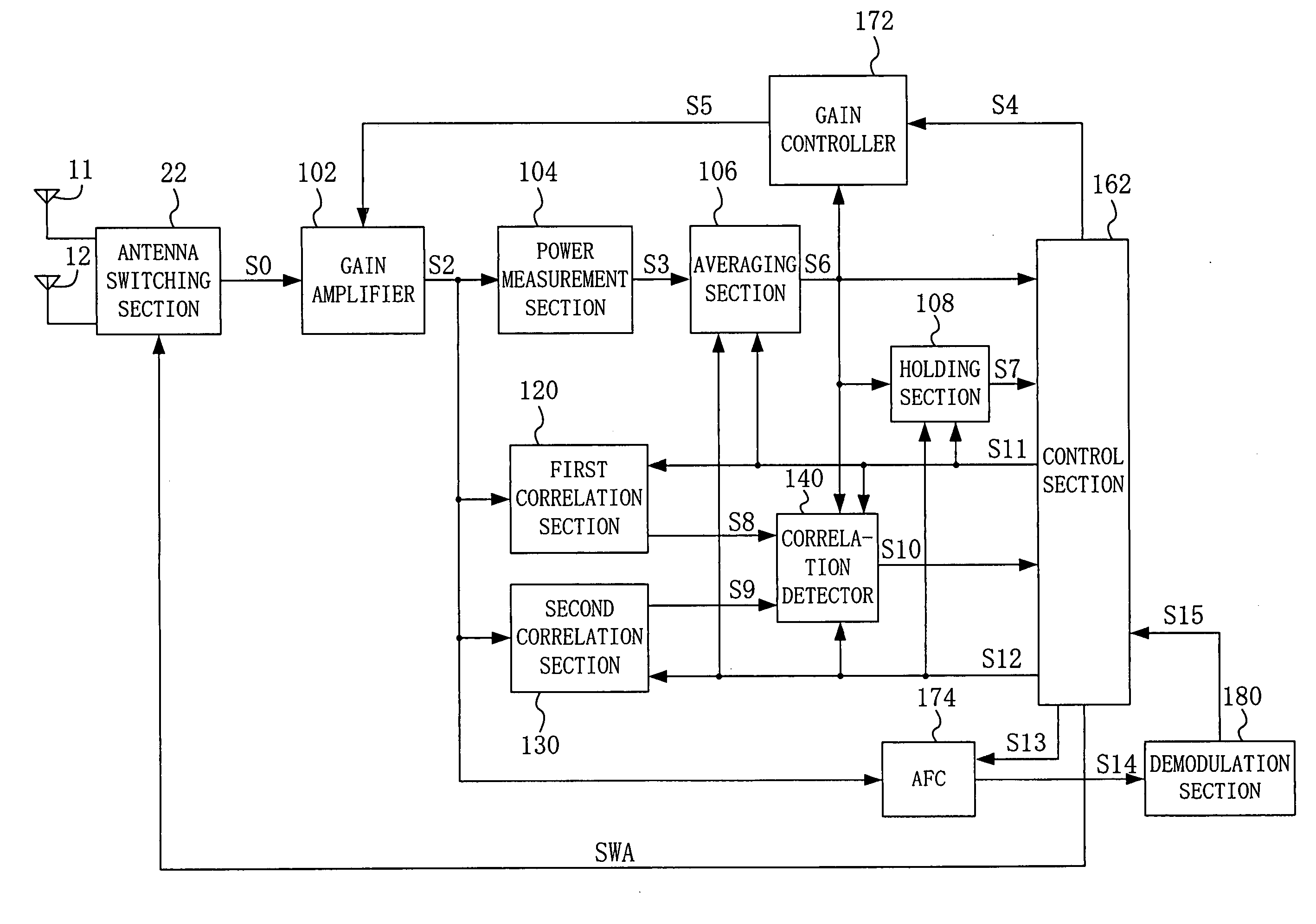
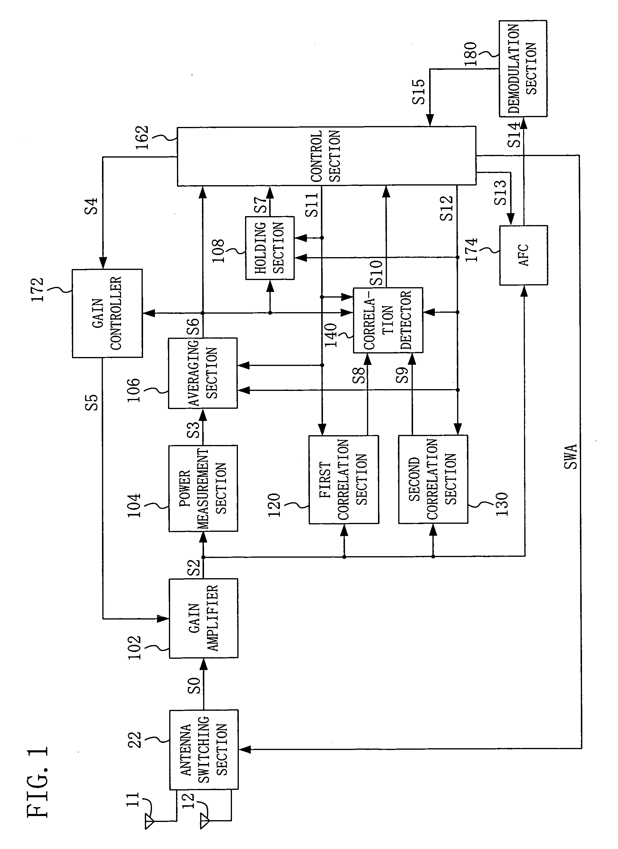
[0048]FIG. 1 is a block diagram of a diversity receiver according to embodiment 1 of the present invention. The diversity receiver of FIG. 1 includes a gain amplifier 102, a power measurement section 104, an averaging section 106, a holding section 108, a first correlation section 120, a second correlation section 130, a correlation detector 140, a control section 162, a gain controller 172, an automatic frequency controller (AFC) 174, and a demodulation section 180. The diversity receiver of FIG. 1 selects any one of a first antenna 11 and a second antenna 12. More specifically, antenna selection signal SWA is generated for an antenna switching section 22 to select any one of signals received through the antennas 11 and 12.

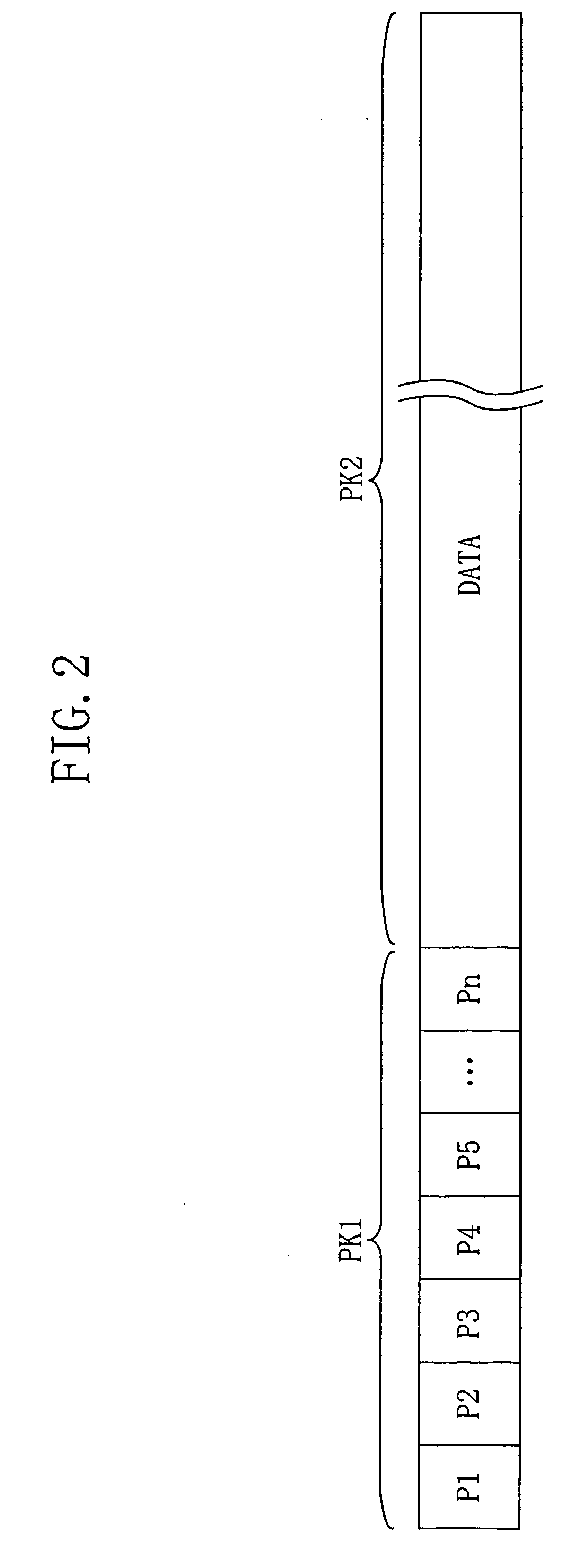
[0049]FIG. 2 shows an example of a structure of a packet received by the diversity receiver of FIG. 1. The packet of FIG. 2 includes preamble part PK1 and data part PK2. Preamble part PK1 includes patterns P1, P2, . . . Pn (n≧2). Each of patterns P1, P2, . . . P...

embodiment 2

[0090]FIG. 13 is a block diagram of a diversity receiver according to embodiment 2 of the present invention. The diversity receiver of FIG. 13 includes a correlation detector 240 and a control section 262 in substitution for the correlation detector 140 and the control section 162 of the diversity receiver of FIG. 1 and further includes a correlation holding section 276. The other elements are the same as those illustrated with reference to FIG. 1 and hence denoted by the same reference numerals, and therefore, the detailed descriptions thereof are herein omitted.

[0091]FIG. 14 is a block diagram showing a structure of the correlation detector 240 of FIG. 13. The correlation detector 240 includes subtractors 245 and 246 and a selector 248 in addition to the components of the correlation detector 140 of FIG. 5.

[0092] In an effective period of first correlation process notice signal S11, the subtractor 245 subtracts average power value S30 from first correlation value S8 and outputs ...


PUM


Abstract

A diversity receiver comprises: a control section for generating an antenna selection signal such that a plurality of antennas are sequentially selected on a one-by-one basis; a plurality of correlation sections which correspond to the plurality of antennas on a one-to-one basis, each of the correlation sections determining a correlation value between a signal received through a corresponding antenna and a predetermined pattern; and a correlation detector for detecting the predetermined pattern in a signal received through each of the plurality of antennas based on a correlation value determined by a corresponding one of the correlation sections and an average power corresponding to the antenna and outputting a detection result. The control section determines an antenna through which a signal including the predetermined pattern detected by the correlation detector is received as the antenna that is to be subsequently selected based on the detection result of the correlation detector.

Description

CROSS-REFERENCE TO RELATED APPLICATION [0001] This application claims priority under 35 U.S.C. §119(a) on Japanese Patent Application No. 2004-364360 filed on Dec. 16, 2004, the entire contents of which are hereby incorporated by reference. BACKGROUND OF THE INVENTION [0002] 1. Field of the Invention [0003] The present invention relates to a diversity receiver and a diversity reception method. Specifically, the present invention relates to a receiver and method for diversity reception wherein an antenna which is to be used for reception is selected among a plurality of antennas. [0004] 2. Description of the Prior Art [0005] In mobile communication, such as wireless LAN (Local Area Network), or the like, the reception performance has been known to significantly deteriorate due to a fading phenomenon, i.e., a tremendous variation in received field intensity which is caused by reflected and / or scattered waves. A wave receiving technique that reduces such an effect of fading is diversit...

Claims


Application Information

Patent Timeline
Patent Type & Authority Applications(United States)
IPC IPC(8): H04L27/06H04L27/08H04L1/02
CPCH04B7/0808H04L1/0045H04L1/0061
Inventor KAWADA, TOMOHARUKIMURA, TOMOHIRO
Owner PANASONIC CORP
Why Eureka
Try Eureka