Wireless communication device, wireless communication system, and wireless communication method

Active Publication Date: 2010-12-02
BUFFALO CORP LTD
View PDF2 Cites 37 Cited by
  • Summary
  • Abstract
  • Description
  • Claims
  • Application Information

AI Technical Summary

Benefits of technology

[0026]The principle of the invention is also applicable to communication between at least two wireless communication devices. In the wireless communication system according to the second aspect of the invention, in the case of detection of radar/radio signals during communication between at least two LANs, the communication channe

Problems solved by technology

There is accordingly a possibility of interference with radio signals used by such equipment.
This problem is not characteristic of the communication in the wireless LAN but is also found in communication between multiple access points, for example, communication in a WDS mode.
In the event of detection of the radio signal other than the wirel

Method used


Image

  • Wireless communication device, wireless communication system,  and wireless communication method
  • Wireless communication device, wireless communication system,  and wireless communication method
  • Wireless communication device, wireless communication system,  and wireless communication method

Examples


first embodiment

(1) First Embodiment

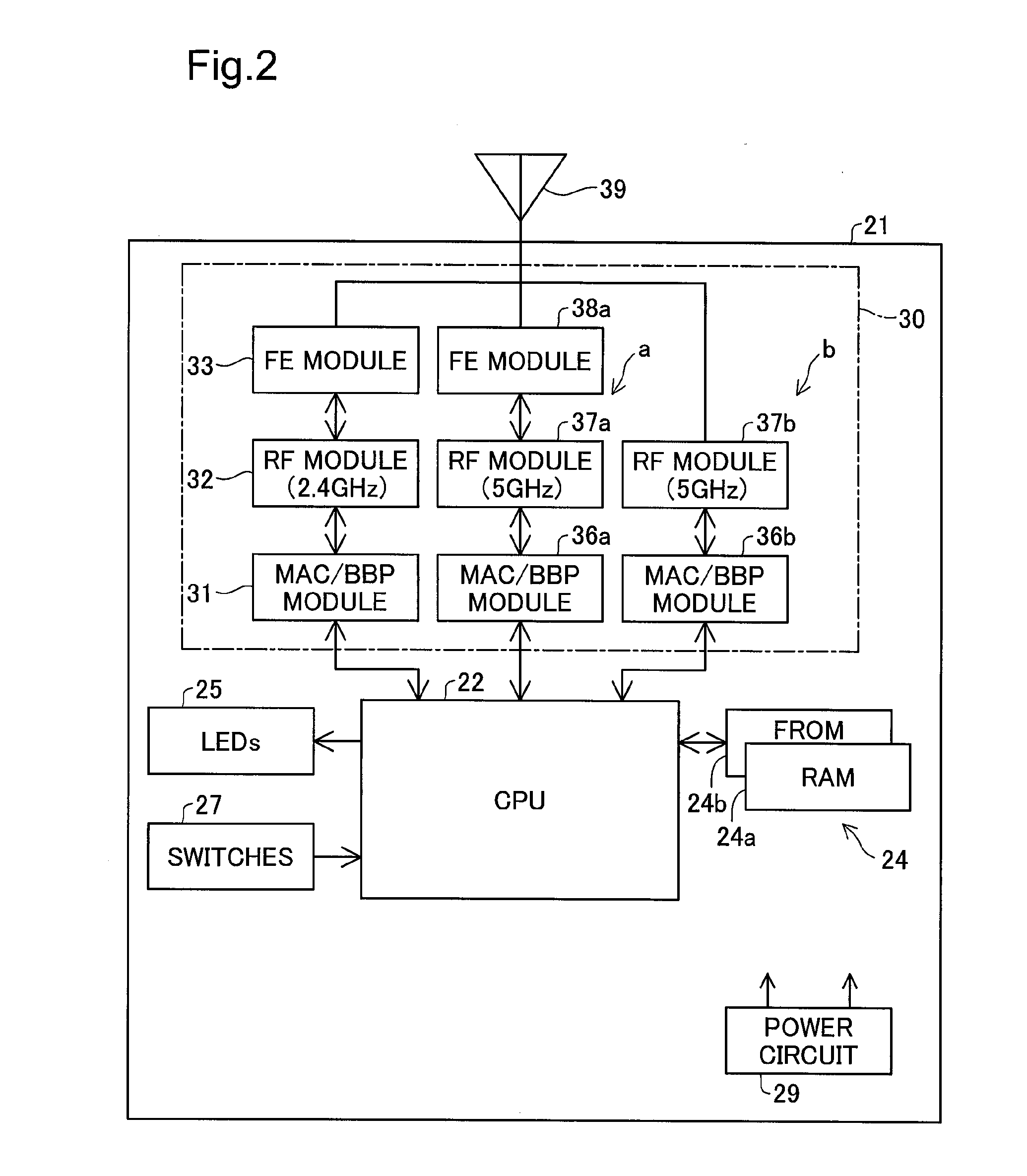
[1] Hardware Configuration of First Embodiment

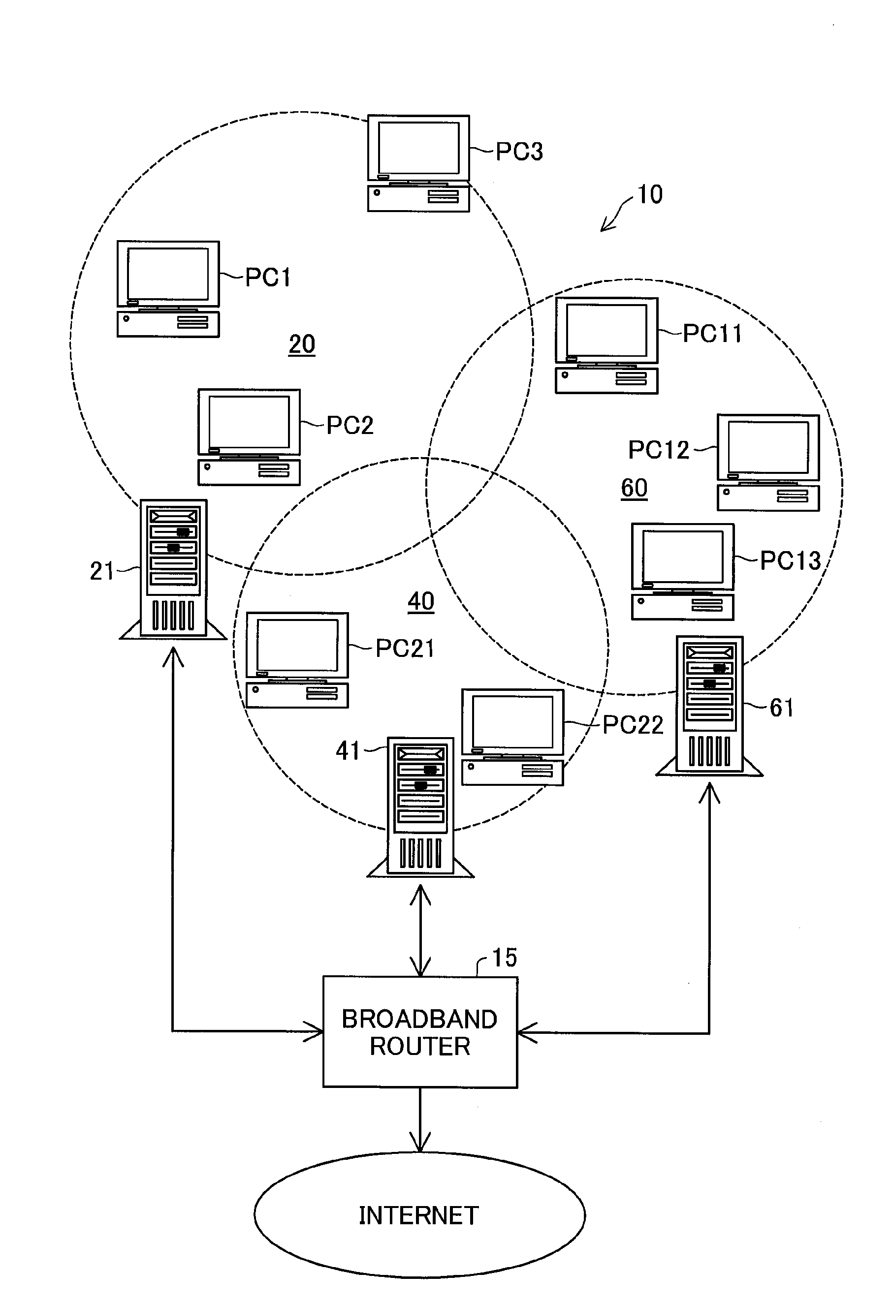
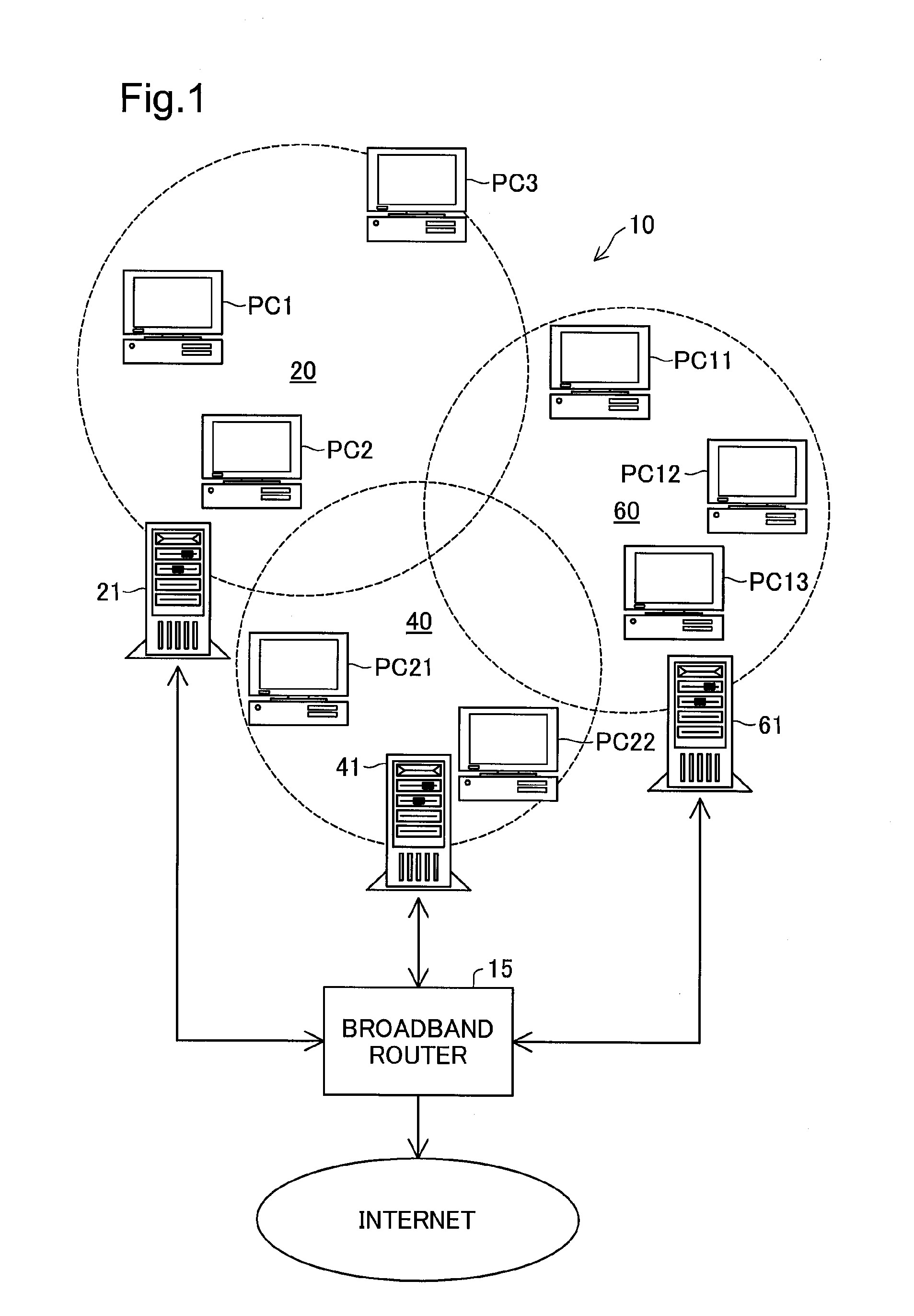
[0038]One mode of carrying out the invention is described below with reference to the accompanied drawings. FIG. 1 is a diagrammatic representation of a system configuration of a wireless LAN system 10 in a first embodiment according to the invention. As illustrated, this wireless LAN system 10 includes a broadband router 15 connecting with an external network, for example, the Internet, and multiple wireless LAN access points 21, 41, and 61 respectively having wired connections to the broadband router 15. The respective access points 21, 41, and 61 are used to establish wireless LANs 20, 40, and 60 that adopt different basic service sets (BSS). These access points 21, 41, and 61 are provided to establish wireless LANs in different areas of a relatively large site for a facility, such as a school or a company. The wireless LANs 20, 40, and 60 have partial overlaps in the coverage of wireless communication, due to the ...

second embodiment

(2) Second Embodiment

[1] Communication Control in Second Embodiment

[0067]A wireless LAN system of a second embodiment according to the invention is described below. The wireless LAN system of the second embodiment has substantially the same configuration as that of the first embodiment shown in FIGS. 1 and 2, except part of the processing performed by the access points 21, 41, and 61. Only the different points from the first embodiment are discussed below.

[0068]The flowchart of FIG. 6 mainly shows a different part of the communication control routine of the second embodiment performed by an access point (for example, the access point 21) from that of the first embodiment. The flowchart of FIG. 7 mainly shows a different part of the monitoring process routine of the second embodiment from that of the first embodiment. As shown in the flowchart of FIG. 6, in the case of non-detection of radar / radio signals, the access point 21 of the second embodiment does not immediately return to th...


PUM


Abstract

An access point establishing a wireless LAN is constructed to have a monitor system ‘b’ for monitoring an available channel for communication, in addition to a communication system ‘a’. In the event of detection of radar/radio signals, the access point changes a communication channel used for wireless communication from a current active channel to the monitored channel. Each terminal belonging to the wireless LAN recognizes and follows this channel change by detection of a beacon broadcasted by the access point. In the case of non-detection of radar/radio signals for one minute at the monitored channel, the wireless communication is reestablished immediately at the monitored channel recognized as a CAC (channel availability check)-finished channel. This series of processing is also applicable to inter-access point communication, for example, communication in a WDS (wireless distribution system) mode. This arrangement desirably prevents the potential interruption of wireless communication in a 5 GHz frequency band for a significant period, in the event of detection of radar/radio signals, for example, a weather radar.

Description

CROSS-REFERENCE TO RELATED APPLICATION[0001]The present application claims priority from Japanese application P2009-129933A filed on May 29, 2009, the content of which is hereby incorporated by reference into this application.BACKGROUND[0002]1. Field of the Invention[0003]The present invention relates to a wireless communication device and a wireless communication method.[0004]2. Description of the Related Art[0005]With improvement of the communication speed and the usability, wireless communication techniques have been used widely in various situations and locations, for example, in the houses, offices, and schools. Wireless communication devices have been proposed to have various functions including broadband router function as well as general access point function (for example, JP-A-No. 2007-325041).[0006]With advance of the wireless communication technology, there is a movement to extend the available range of carrier waves for wireless communication. This movement gives permiss...

Claims


Application Information

Patent Timeline
IPC IPC(8): H04W24/00
CPCG01S7/021H04W16/14
Inventor MATSUURA, NAGAHIRO
Owner BUFFALO CORP LTD
Why Eureka
Try Eureka