Radio Communication System Using Multi-Antenna Transmission Technique, and Multi-User Scheduler Therefor

a radio communication system and multi-antenna transmission technology, applied in multiplex communication, signalling characterisation, wireless commuication services, etc., can solve the problem of difficult to simultaneously control both methods using a single common pilo

Inactive Publication Date: 2008-11-20
FUJITSU LTD
View PDF14 Cites 36 Cited by
  • Summary
  • Abstract
  • Description
  • Claims
  • Application Information

AI Technical Summary

Benefits of technology

[0023]Further, it is possible to configure the receiving station to obtain a reception weight Wrx of a least mean square error (MMSE) solution, using the transmission weight Wtx obtained from the scheduler management channel and the channel estimation value obtained from the received pilot channel, and to perform signal synthesis in regard to the plurality of antennas using the obtained reception weight Wrx.

Problems solved by technology

However, conventionally, the MIMO multiplexing and beamforming have been recognized as independent techniques because of the passage of different propagation paths, and a study taking mutual fusion into consideration has hardly been made.
Namely, in the beamforming mode, because transmission weighting is made, a passing propagation path is different from that in the MIMO multiplexing, and accordingly, it is difficult to simultaneously control both methods using a single common pilot.

Method used


Image

  • Radio Communication System Using Multi-Antenna Transmission Technique, and Multi-User Scheduler Therefor
  • Radio Communication System Using Multi-Antenna Transmission Technique, and Multi-User Scheduler Therefor
  • Radio Communication System Using Multi-Antenna Transmission Technique, and Multi-User Scheduler Therefor

Examples


embodiment 1

[0123]As an embodiment 1, the description is made in regard to a transmitting station in the implementation example listed as a group 1 of Table 1 as shown in FIG. 10, and in regard to a receiving station as shown in FIG. 11.

[0124][Transmitting Station]

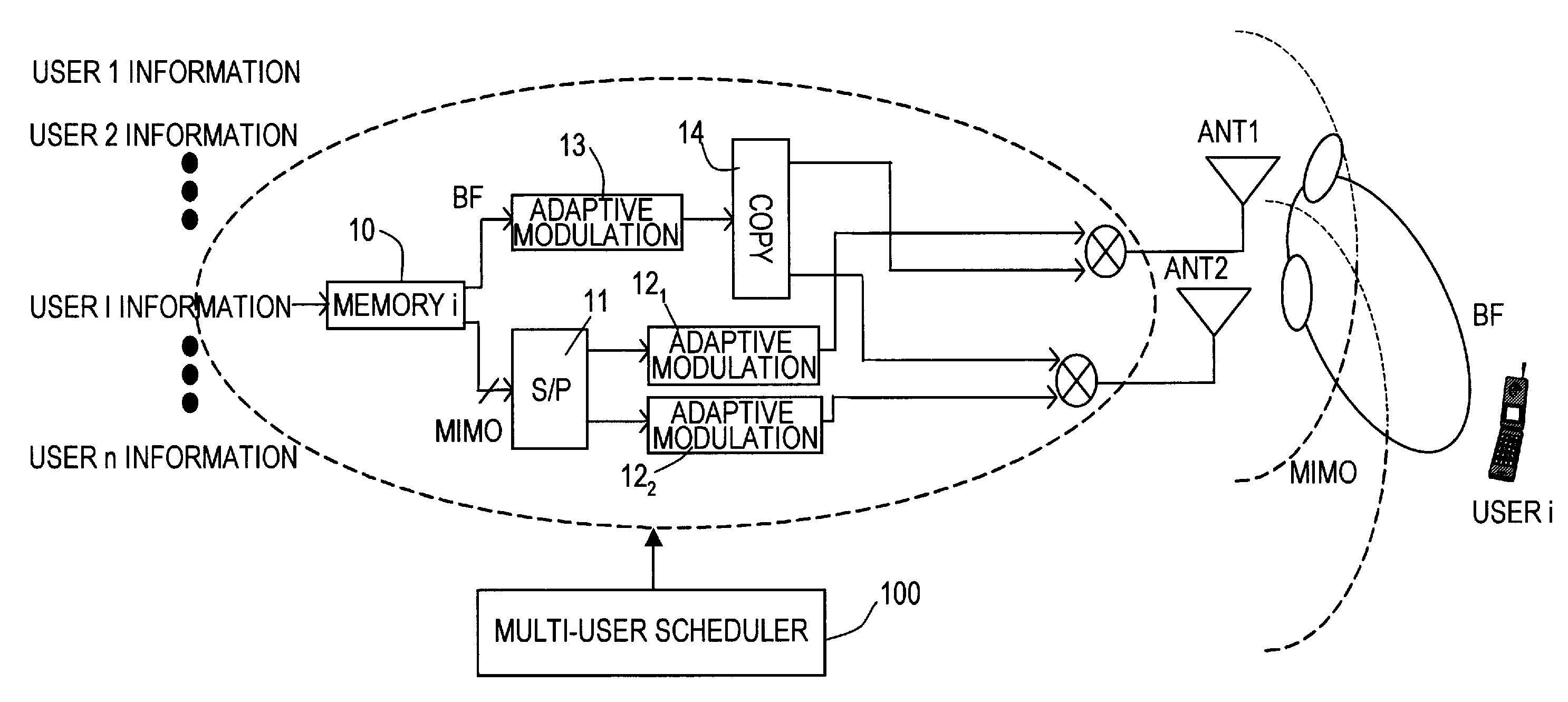
[0125]In a transmitting station communicating with a plurality (n) of users, the data of the above plurality (n) of users are stored in advance in (n) memories 101-10n.

[0126]There is a mechanism of reading out data from memories 101-10n according to a request from a scheduler 100. Here, from the receiving station (refer to FIG. 11) of each user, feedback information is returned so as to report space propagation path information and the validity / invalidity of the transmitted data.

[0127]Scheduler 100 is operated by totaling the above information for the entire users. In FIG. 10, only a feedback information reception section 110 for one user is shown.

[0128]For example, an example of time multiplexing of each channel is shown in FIG. 10 a...

embodiment 2

[0187]Next, an embodiment 2 corresponding to the group 2 in Tables 1, 2 is described. FIGS. 15 and 16 show exemplary configurations of a transmitting station and a receiving station, respectively, corresponding to the embodiment 2.

[0188][Transmitting Station]

[0189]In FIG. 15, description is made with attention directed to the points of difference from the transmitting station according to the embodiment 1 shown in FIG. 10. The feature of the transmitting station corresponding to the embodiment 2 shown in FIG. 15 lies in that only information is reflected in scheduler 100 when the ZF solution is obtained from the channel matrix H fed back from the receiving station.

[0190]Also, because of a configuration reporting only the transmission weight wtx, it is different from the embodiment 1 in that a weight reported from scheduler management information generation section 102 is performed using Wtx.

[0191][Receiving Station]

[0192]Corresponding to the above modification in the transmitting st...

embodiment 3

[0195]An embodiment 3 corresponding to the group 3 shown in Tables 1, 2 is described. FIGS. 17 and 18 show exemplary configurations of a transmitting station and a receiving station, respectively, corresponding to the embodiment 3.

[0196][Transmitting Station]

[0197]As compared to the embodiment 2, in the embodiment 3, there is a difference only in the point that the information to be fed back is not the channel matrix H but a transmission weight (Wtx) 115d. As an improved point, the information amount to be fed back can be reduced. Also, as an advantageous point, it is also possible to point out that the calculation amount in the transmitting station can be reduced.

[0198][Receiving Station]

[0199]In the receiving station, as contrasted with the receiving station configuration of the embodiment 2 shown in FIG. 16, there is a difference in that, in regard to the information to be fed back, a ZF solution 231 obtained from the channel matrix H 221 by use of expressions (7), (8) is calcula...


PUM


Abstract

In a radio system performing scheduled transmission to a plurality of receiving stations from a transmitting station having a plurality of antennas, a transmitting station obtains reception quality information estimated from feedback information obtained from the plurality of receiving stations, determines a transmission system whether to perform beamforming, which transmits data of an identical stream by weighting each of the plurality of antennas based on the obtained reception quality information, or to perform MIMO multiplexing, which transmits data of different streams respectively from the plurality of antennas, and transmits information to identify the determined transmission system by adding to a scheduler management channel.

Description

CROSS REFERENCE TO RELATED APPLICATIONS[0001]This application is a continuation of International Application No. PCT / JP2006 / 302174, filed on Feb. 8, 2006, now pending, herein incorporated by reference.FIELD OF THE INVENTION[0002]The present invention relates to a radio communication system using a multi-antenna transmission technique, and a multi-user scheduler to be applied thereto.BACKGROUND ARTS[0003]In the radio communication, as a technique of using a plurality of transmission and reception antennas (multi-antenna), there have been studied a technique of transmission by a multiplicity of antennas and reception by a multiplicity of antennas (MIMO: Multi Input Multi Output) in which different streams are transmitted from each antenna, thereby improving throughput, and a beamforming (which may be represented as BF hereinafter in an appropriate time) technique in which multiplex transmission is performed by weighting an identical stream, thereby improving reception quality (Non-pat...

Claims


Application Information

Patent Timeline
Patent Type & Authority Applications(United States)
IPC IPC(8): H04J3/00H04Q7/20H04J99/00H04W16/00H04W16/24H04W72/04H04W72/12
CPCH04B7/0632H04B7/0634H04B7/0658H04W72/1205H04B7/0871H04W72/046H04B7/0689H04W72/12H04B7/0413H04B7/0617H04B7/063H04L1/0026
Inventor YOKOYAMA, HITOSHI
Owner FUJITSU LTD
Why Eureka
Try Eureka