
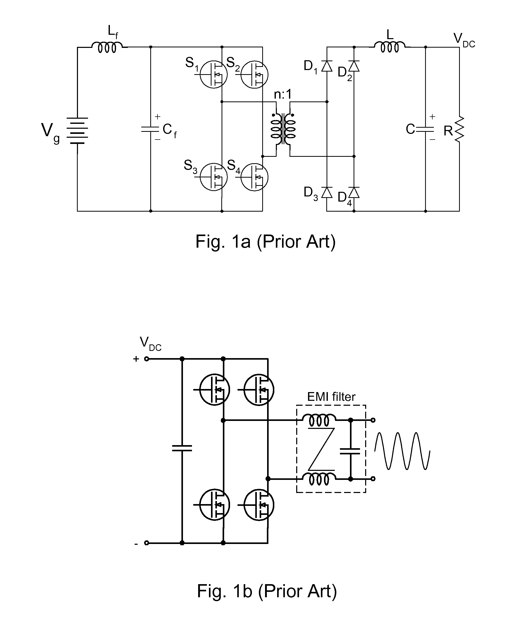
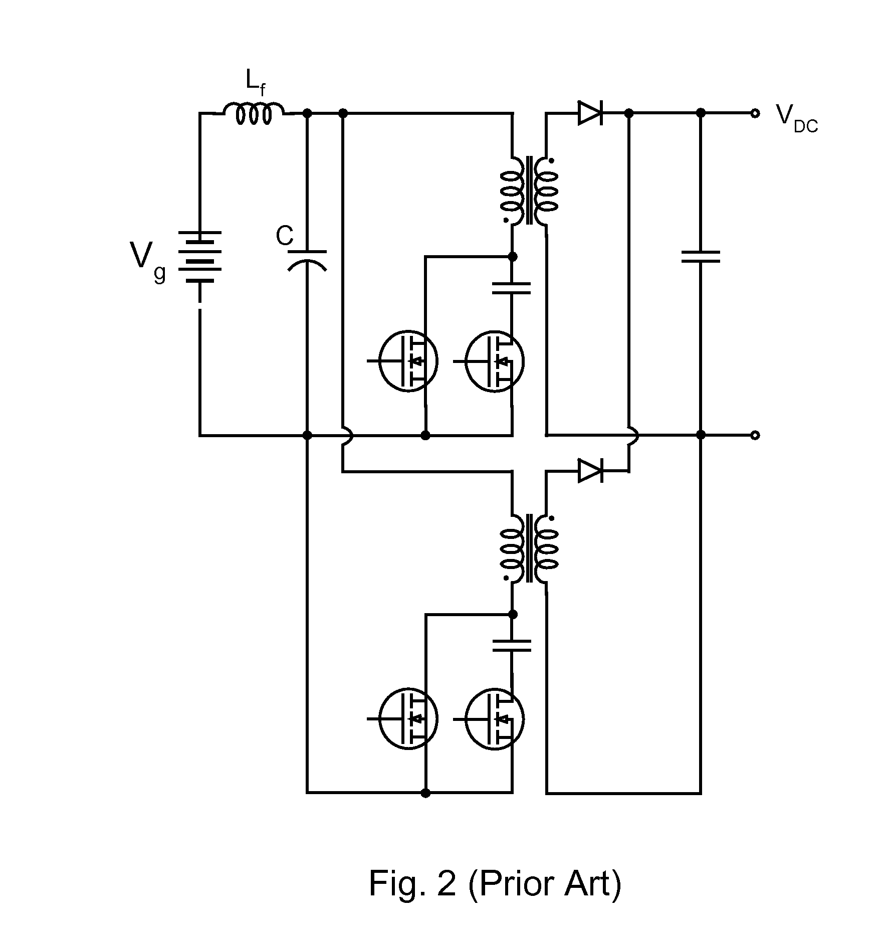
Single-stage inverter with high frequency isolation transformer

Inactive Publication Date: 2012-10-18
CUKS
View PDF2 Cites 30 Cited by
  • Summary
  • Abstract
  • Description
  • Claims
  • Application Information

AI Technical Summary

Benefits of technology

[0093]The present DC-AC inverters based on the flyback and bridge-type DC-DC converter topologies have performance and efficiency drawbacks due to the losses incurred in the energy stored in the transformer leakage inductance, which must be removed by use of dissipative snubers. The present invention in FIG. 3a eliminates the losses due to the leakage inductance of the isolation transformer. Note the presence of the resonant inductor with the primary of the isolation transformer. Due to the capacitive charge and resonant discharge of the primary resonant capacitor, the energy stored in the leakage inductance during the ON-time interval is released in a non-dissipative wave during the OFF-time resonant interval. This also eliminates any spikes on switches usually present in conventional DC-DC converters. This clearly leads to both higher efficiency and permits operation at higher switching frequencies to reduce the size of the magnetic components.
[0094]The two switches on the transformer primary side are operated so that there are two transition intervals during which bo

Problems solved by technology

In true resonant converters the original square-wave voltage waveforms are distorted by resonance into sinusoidal waveforms with much larger peak values, resulting in much increased voltage stresses on switches.
Note also how the Hybrid-switching method results in very small size of resonant inductor.
This is clearly not allowed in either square-wave or conventional resonant converters.
Although simply varying the air-gap could change resonant inductor values, this clearly mechanical approach would not work.
Two other possible placements of the resonant inductor are also shown in FIG. 27a and FIG. 27b but with possibly inferior performance.
The drawback is that this would also impose an additional constraint on the design, as the resonant inductor value could not be chosen to optimize design.
Note however, that despite large DC voltage level of each capacitor, the net voltage on two capacitors in series is their difference thus resulting in only an ac voltage mismatch of Δv as shown in FIG. 30c, which therefore leads to the same resonant converter analysis for the non-isolated converter derived before.
All single-sided (non-bridge type on primary side) prior-art converters with step-down DC gain characteristic of D, resulted in a non-ideal transformer features such as:1. DC energy storage in transformer such as Asymmetric Half-Bridge (AHB) converter;2. Transformer whose excitation in the high duty ratio range results in very high reset voltage and correspondingly high voltage stresses on the switches as well as very limited input voltage range.
The bridge-type

Method used


Image

  • Single-stage inverter with high frequency isolation transformer
  • Single-stage inverter with high frequency isolation transformer
  • Single-stage inverter with high frequency isolation transformer

Examples


Example

[0095]In some applications no isolation is required, nor the voltage scaling by the transformer turns ratio. In that case Single-Stage inverter can be further simplified by shorting the transformer and combining two capacitors in series to result in a single capacitor and a Single-Stage non-isolated DC-AC inverter shown in FIG. 6a, which also eliminates the need for the unfolding four transistors full bridge stage.

[0096]FIG. 6b shows another implementation of the composite switch comprising S2 and S3 switches but this time using the two switches connected in parallel and each switch implemented by a Reverse Blocking IGBT (RBIGBT) transistors. Note that that this composite switch operates so that S3 switch operates in first quadrant for positive polarity output voltage and is OFF for negative output voltage polarity. The switch S4 on the other hand operates in third quadrant for negative output voltage polarity and is OFF for positive output voltage polarity.

Basic Operation and Analy...


PUM


Abstract

The novel single-stage power processing DC-AC inverter topology with high frequency isolation transformer eliminates the four-transistor unfolding full-bridge stage and provides the output AC voltage at high power conversion efficiency. The new inverter topology has only three switches, two resonant capacitors, a resonant inductor, an output inductor and a small size high-frequency isolation transformer, which does not store the DC energy. The output AC voltage is obtained by the PWM sinusoidal modulation of the duty ratio control of the three switches and can be regulated against the input voltage changes.

Description

FIELD OF THE INVENTION[0001]The present invention belongs to the category of DC-AC inverters, which convert DC input power, such as from solar cells source and generate an alternating AC power, which is interfaced directly to the utility line to provide the active power to the residential loads. Such High-frequency Isolated Utility Interactive inverters (1,2) are at present composed of two power-processing stages:[0002]1. Conventional isolated DC-DC converter, which is modulated by the duty ratio to generate the 60 Hz rectified AC voltage on the output.[0003]2. The second stage consisting of the four transistors full-bridge converter to result in the 60 Hz sine-wave output voltage which is then interfaced to the utility line.[0004]This two-stage processing is necessitated due to the lack of the converters which can directly convert DC input power to AC, as present DC-DC converters can only generate output DC voltage of one polarity only.[0005]What is needed for direct conversion of ...

Claims


Application Information

Patent Timeline
IPC IPC(8): H02M7/537
CPCH02M7/4807
Inventor CUK, SLOBODAN
Owner CUKS
Learn More