Injection Mold

a technology of injection molds and injection plates, applied in the field of injection molds, can solve the problems of low production of products, and achieve the effect of avoiding broken bars and ensuring product production

Inactive Publication Date: 2012-10-18
CHENG UEI PRECISION IND CO LTD
View PDF15 Cites 12 Cited by
  • Summary
  • Abstract
  • Description
  • Claims
  • Application Information

AI Technical Summary

Benefits of technology

[0007]As described above, the injection mold utilizes the maintaining pillar to always resist against the bottom of the sliding block during the bars being parted from the shaping grooves to prevent the ejector pin plate moving upward so as to avoid the ejector pin moving upward. So it effectively avoids the bars being broken off the product and further assures the production of the product.

Problems solved by technology

As a result, the bars of the product are apt to be broken so that causes a low production of the product.

Method used


Image

  • Injection Mold
  • Injection Mold
  • Injection Mold

Examples


Embodiment Construction

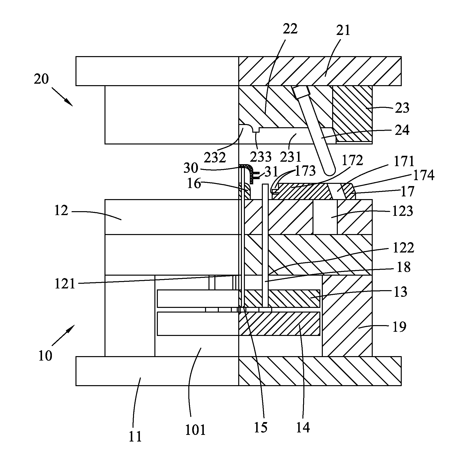
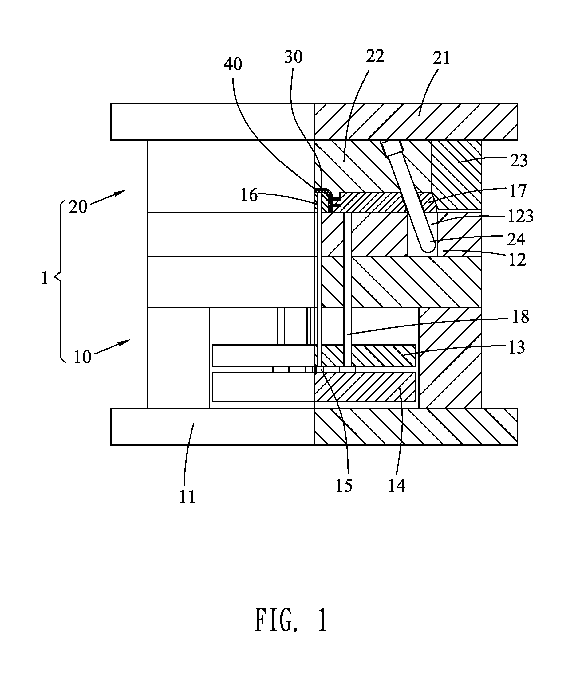
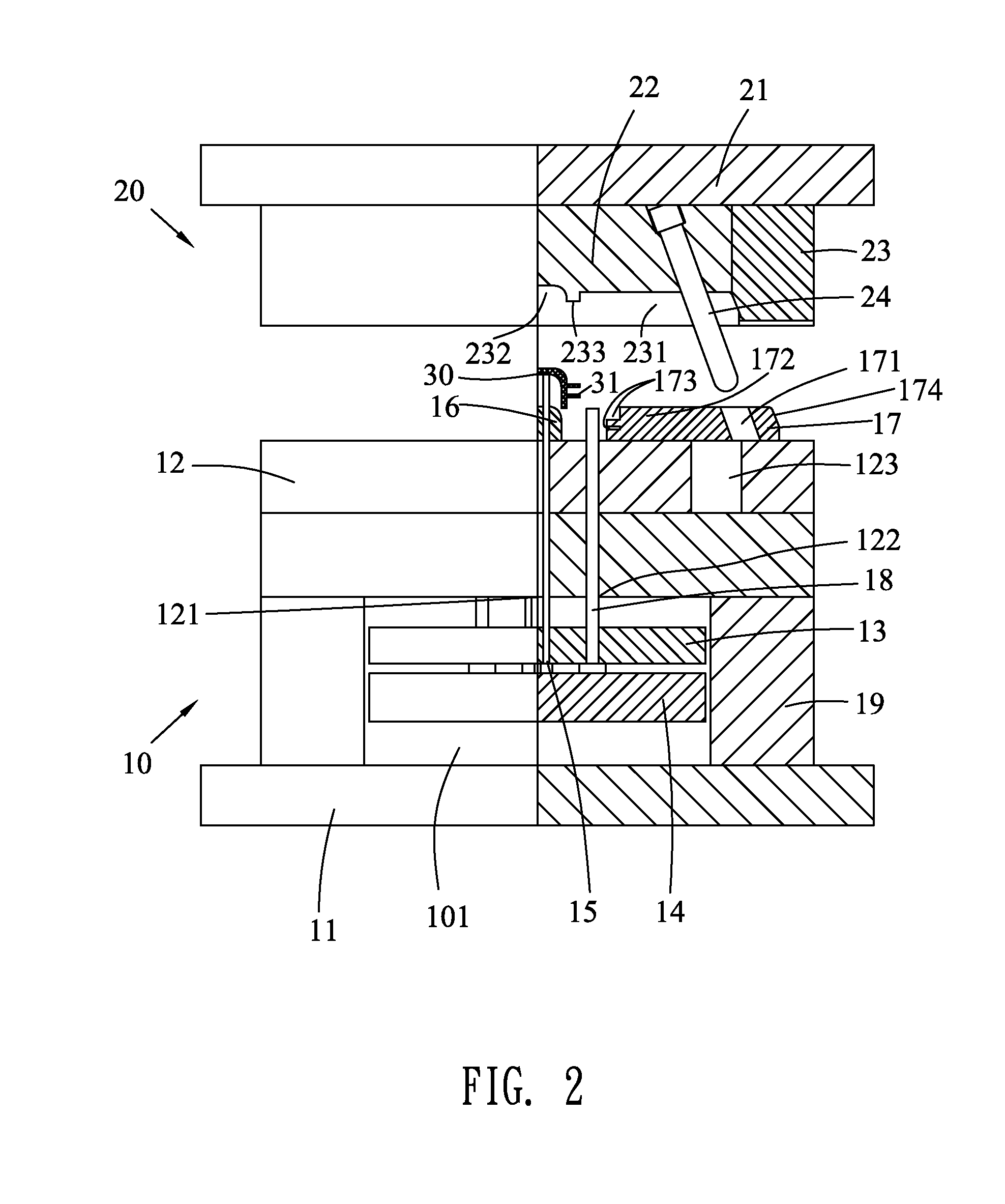
[0011]Referring to FIG. 1, an embodiment of an injection mold 1 according to the present invention is shown. The injection mold 1 adapted for molding a product 30 includes a movable mold 10 and a stationary mold 20 positioned over the movable mold 10.

[0012]Referring to FIGS. 1-2, the movable mold 10 includes a movable fixing plate 11, a movable plate 12, an ejector pin plate 13, an ejector pin fixing plate 14, an ejector pin 15, a movable core 16 mounted on a top of the movable plate 12, a sliding block 17, a maintaining pillar 18 and two support blocks 19. The movable fixing plate 11 is disposed levelly. The two support blocks 19 are mounted on two opposite sides of a top of the movable fixing plate 11 and spaced from each other. The movable plate 12 is mounted on tops of the two support blocks 19. A space 101 is formed among the movable fixing plate 11, the two support blocks 19 and the movable plate 12. The ejector pin fixing plate 14 is located in the space 101 and above the mov...


PUM

PropertyMeasurementUnit
rectangular shapeaaaaaaaaaa
timeaaaaaaaaaa

Abstract

An injection mold for molding a product having at least one bar formed at one side thereof. The injection mold includes a stationary mold including an inclined pillar and a movable mold including a movable core and a sliding block mounted on a top thereof. The inclined pillar inserted in the sliding block to drive the sliding block to slide towards or away from the movable core. A shaping cavity for molding the product is formed among the movable core, the sliding block and the stationary mold. The end surface of the sliding block further defines at least one shaping groove connected with the shaping cavity for molding the bar. The movable mold further includes an ejector pin and a maintaining pillar. The maintaining pillar resists against a bottom of the sliding block to avoid the ejector pin moving upward before the bar completely parted from the shaping groove.

Description

BACKGROUND OF THE INVENTION[0001]1. Field of the Invention[0002]The present invention generally relates to an injection mold, and more particularly to an injection mold capable of ejecting a product out effectively.[0003]2. The Related Art[0004]Generally, a conventional injection mold for molding a product having two bars protruding sideward from one side thereof includes a stationary mold and a movable mold. The movable mold includes a movable plate, an ejector pin fixing plate, an ejector pin, a movable core mounted in a middle of a top of the movable plate, and a sliding block mounted on one side of the top of the movable plate. The sliding block defines an inserting perforation extending slantwise in one end thereof, and two grooves at the other end thereof and apart facing the movable core. A bottom end of the ejector pin is fastened to the ejector pin fixing plate, and a top end of the ejector pin can movably penetrate through the movable plate and the movable core. An incline...

Claims


Application Information

Patent Timeline
Patent Type & Authority Applications(United States)
IPC IPC(8): B29C45/03
CPCB29C45/2628B29C45/40B29C45/33
Inventor GONG, WEN-PENGWU, XIAO-PINGCHIANG, KUN-HSUEH
Owner CHENG UEI PRECISION IND CO LTD
Why Eureka
Try Eureka