Electrical Test Apparatus

a test apparatus and circuit technology, applied in the direction of electric connection testing, measurement devices, instruments, etc., can solve the problems of equipment that was electrically connected to an outlet and catastrophically failed, equipment not being within specifications, and familiarity in the electrical power arts may not be enough

Inactive Publication Date: 2012-10-25
LEE ROBERT +1
View PDF4 Cites 35 Cited by
  • Summary
  • Abstract
  • Description
  • Claims
  • Application Information

AI Technical Summary

Benefits of technology

[0012]There is a plug tester for checking the NEMA 5-15 receptacle, the common household receptacle in America, that tells whether the outlet has power and whether it is wired correctly. There have been cases encountered where that type of receptacle was incorrectly electrically connected to 277 volts and had that tester light up normally with the same light intensity and not have the tester damaged, thus indicating an OK circuit, when in fact it should have been 120 volts. This has resulted in equipment catastrophically failing that was electrically connected to that outlet before the problem was discovered. Of course, any equipment, especially electronic equipment, designed to be connected to 120 volts plugging into that too high of voltage.
[0013]There remains the need for an electrical test apparatus that is designed to be more of a “fail safe” device in operation, thus always affirmatively indicating acceptable electrical parameters have been meet and to always affirmatively indicate whenever unacceptable test results occur. This means that a light just simply cannot indicate the presence of voltage (which could be too high or too low) or having a “no light on” condition to indicate a particular operational state-wherein it would not be known in the particular operational state was meeting or just that the circuitry or light was inoperative, thus there needs to be a specific colored light for each one of many anticipated electrical conditions. Thus, simply “Green illuminated is good. Not green (having another color indication illuminated), being not good” is desirable for an affirmative electrical condition indication.
[0014]The present invention utilizes a programmable circuit board that has been developed for utilizing multiple changing color single LEDs as indicators to determine voltage levels at several points simultaneously and at a quick and easy glance convey that information to the electrical test apparatus user. The typical light indicators are green for within a nominal voltage range, yellow for lower and red for above range or out of range. This is accomplished by measuring the peak of a sine wave and comparing it to predetermined and programmable values in a microprocessor register. It has been used in a receptacle tester for a great variety of single and three phase receptacles, but can also be used to monitor voltages of an electrical system by anyone, not only those familiar in the electric power arts.
[0015]A test procedure for a 120 volt nominal typical system would show the following results. The circuit board would have three input wires and three functioning LED's. The circuit board would be programmed to respond to these 3 input wires only. When the circuit board is connected to a variable 120 volt alternating current (VAC) source, the board would expect to see voltage between the hot (L1...

Problems solved by technology

However, it takes someone familiar in the power electrical arts to know if the value read on the meter is appropriate for the particular point of an electrical outlet, especially given the great variety of electrical receptacles, and when there exists a specialized receptacle like a twist lock type, including three phase, even those familiar in the electrical power arts ...

Method used


Image

  • Electrical Test Apparatus
  • Electrical Test Apparatus
  • Electrical Test Apparatus

Examples


Embodiment Construction

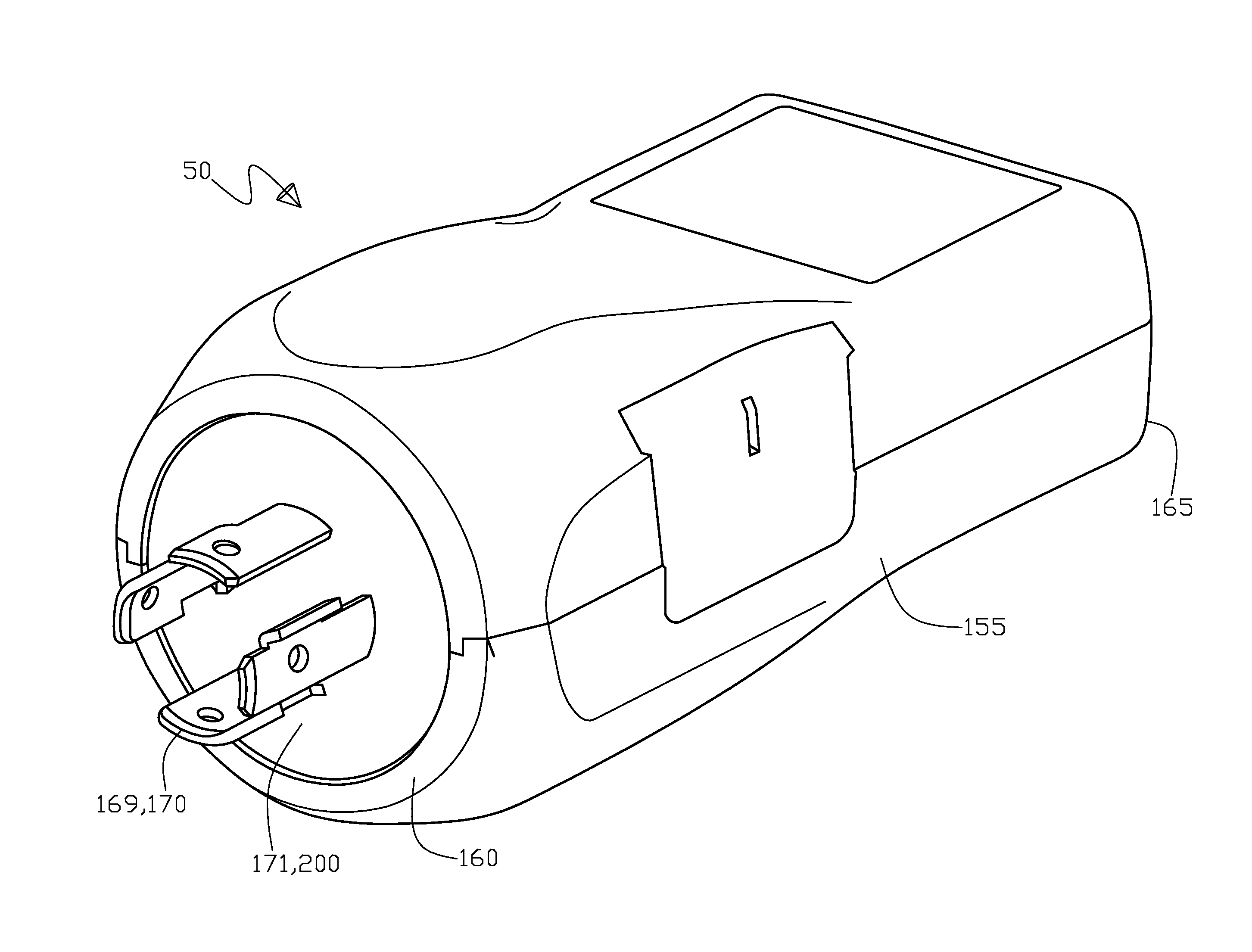
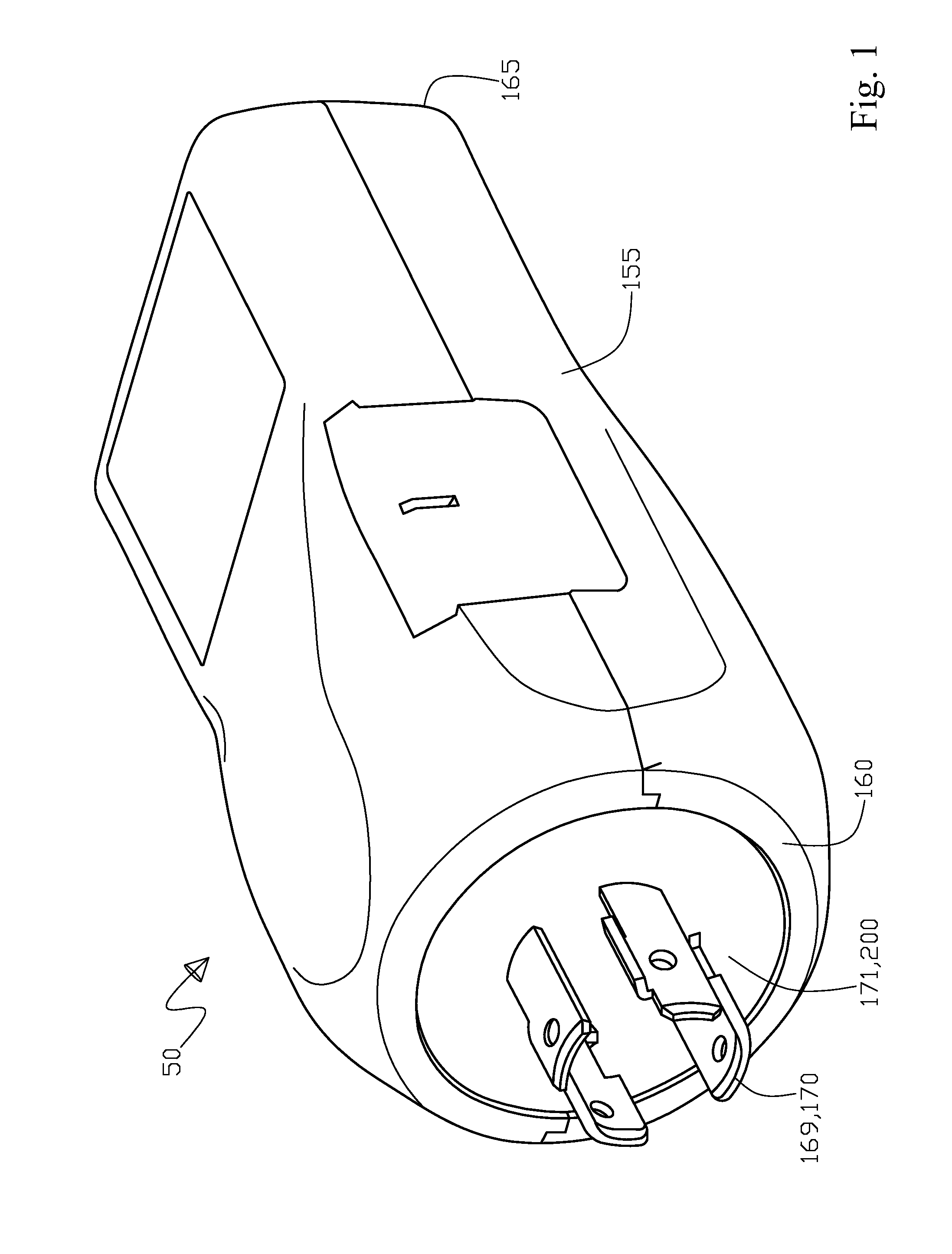
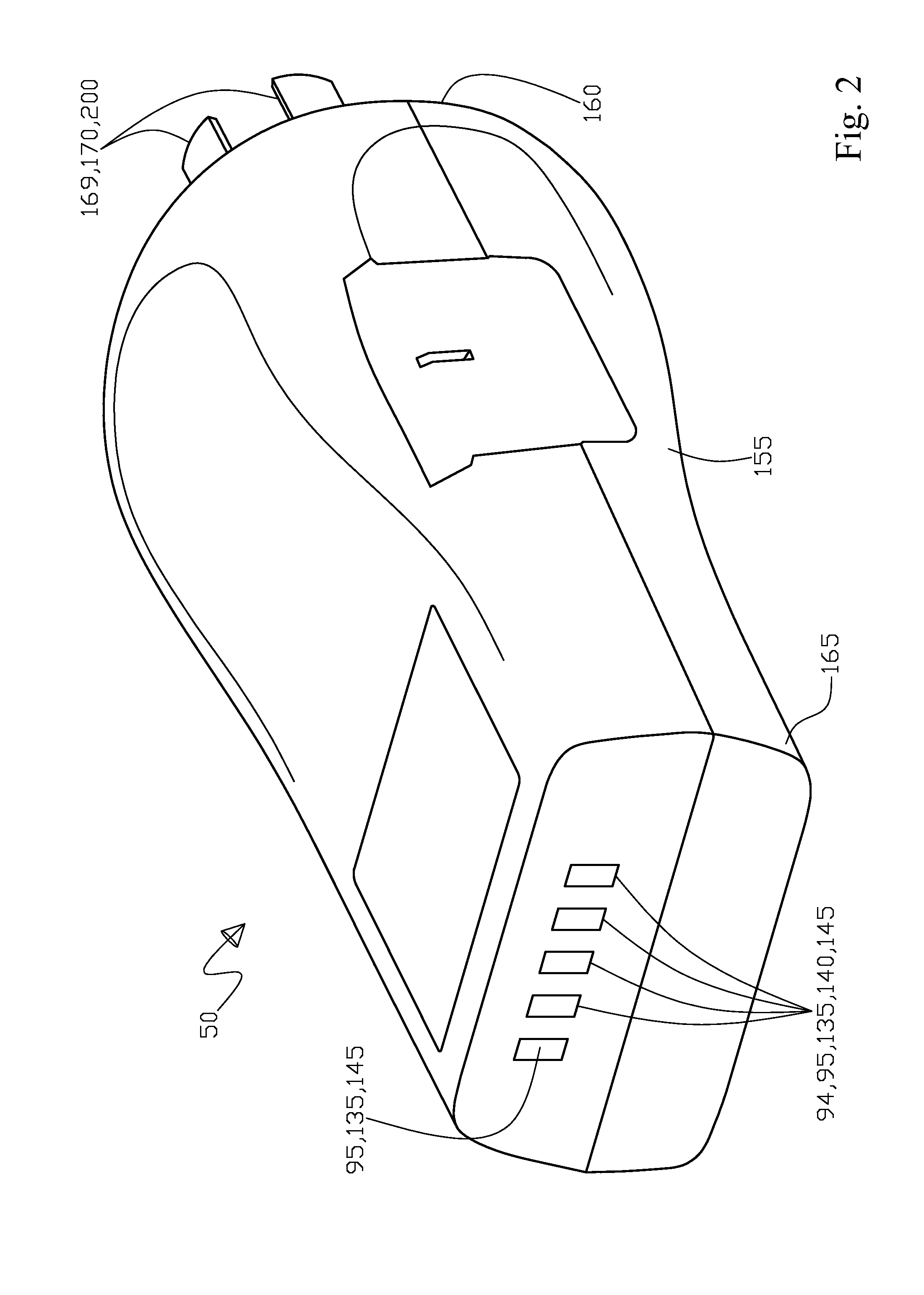
[0072]With initial reference to FIG. 1 shown is a perspective view of the electrical test apparatus 50 with the first end portion 160 of the housing 155 facing frontward with an adaptor 171 for different multiple prong connections 169 for a plurality of unique multiple prong groups 200, that show a multiple prong connector of a twist lock type 170, further the second end portion 165 of the housing 155 is shown. Continuing, FIG. 2 shows an opposing perspective view of the electrical test apparatus 50 from FIG. 1, with FIG. 2 showing a second end portion 165 facing frontward of the housing 155 with the visual display 135 of either the single always illuminated LED light 95 or alternatively a plurality of always status indicating illuminated LED lights 140 plus the first end portion 160 of the housing 155 facing rearward, that show a multiple prong connector 169 of a twist lock type 170. Next, FIG. 3 shows an exploded perspective view of the electrical test apparatus 50 with the housin...


PUM


Abstract

Broadly, the present invention is an electrical test apparatus that is adapted to be removably engaged and in electrical communication with an electrical power terminal, the electrical test apparatus includes analytical circuitry that is operative in each of a plurality of modes to monitor the electrical power terminal and produce a plurality of event marker signals. Further included is a criterion circuitry that is operative in each of the plurality of modes to receive each of the plurality of event marker signals for a comparison with a selected value for each of the plurality of modes, wherein the criterion circuitry outputs a plurality of perceptive signals each corresponding to one of the plurality of modes. In addition, a structure is included for producing an associated perceptible output in response to each of the plurality of perceptive signals.

Description

RELATED PATENT APPLICATIONS[0001]This is a continuation in part (CIP) patent application of U.S. patent application Ser. No. 12 / 390,460 filed on Feb. 21, 2009 by Rodney Hibma et al. of Golden, Colo. US, that in turn claims benefit of U.S. provisional patent application Ser. No. 61 / 066,477 filed on Feb. 21, 2008 by Rodney Hibma of Golden, Colo. US, Robert Lee of Golden, Colo. US, Ammon Balaster of Boulder, Colo. US, and Jeffrey Buske of Las Vegas, Nev. US.TECHNICAL FIELD[0002]The present invention generally pertains to the field of electrical circuit test apparatus and more particularly to a portable plug-in electrical power line test module electrical circuit tester, including a power line analyzer with the electrical test apparatus adapted to removably engage a common electrical power receptacle. Test examples would include to analyze power line voltages, neutral, ground circuit conditions, and phase rotation.BACKGROUND OF INVENTION[0003]Portable electrical power analyzers exist in...

Claims


Application Information

Patent Timeline
IPC IPC(8): G01R31/00
CPCG01R15/125G01R31/04G01R19/16547G01R31/66
Inventor LEE, ROBERTHIBMA, RODNEY
Owner LEE ROBERT
Why Eureka
Try Eureka