Apparatus and system for providing wireless charging service

a wireless charging and wireless charging technology, applied in the field of electronic devices, can solve the problems of users' inconvenience and no further progress in battery charging, and achieve the effect of stable wireless charging service and efficient control of charging rights

Active Publication Date: 2012-10-25
LG ELECTRONICS INC
View PDF3 Cites 340 Cited by
  • Summary
  • Abstract
  • Description
  • Claims
  • Application Information

AI Technical Summary

Benefits of technology

[0007]Therefore, an aspect of the detailed description is to provide a wireless charging apparatus and system, capable of providing a user with a stable wireless charging service by efficiently controlling charging rights for a plurality of electro...

Problems solved by technology

However, further progress in battery charging has not been made in spite of those approaches or attempts for enhancement of the battery efficiency.
Especially, in order ...

Method used


Image

  • Apparatus and system for providing wireless charging service
  • Apparatus and system for providing wireless charging service
  • Apparatus and system for providing wireless charging service

Examples


first embodiment

[0110]FIGS. 4A and 4B are perspective views exemplarily showing a charging apparatus for charging a plurality of electronic devices in accordance with a

[0111]Referring to FIG. 4A, a charging apparatus 100 for charging a plurality of electronic devices can be a pad type.

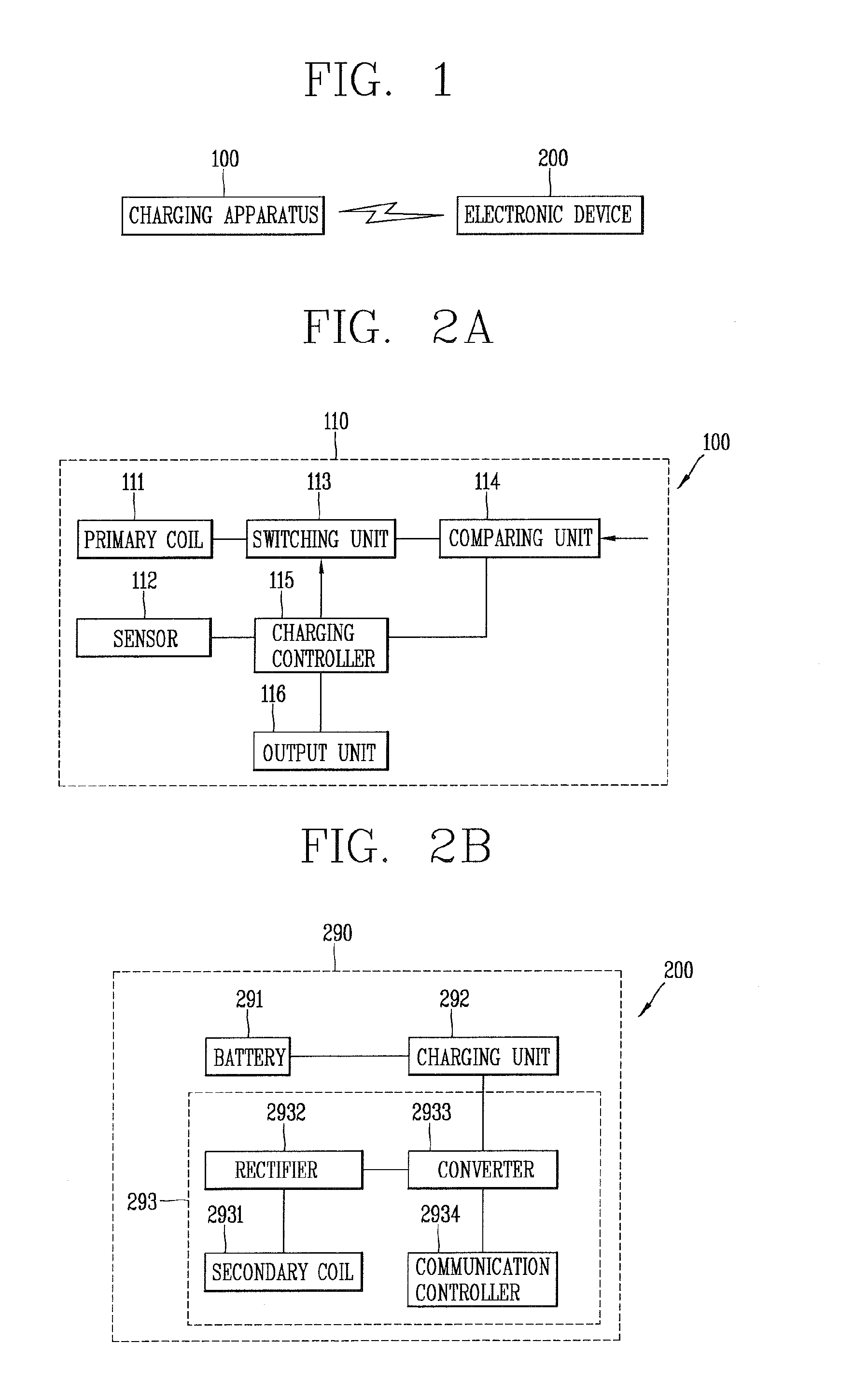
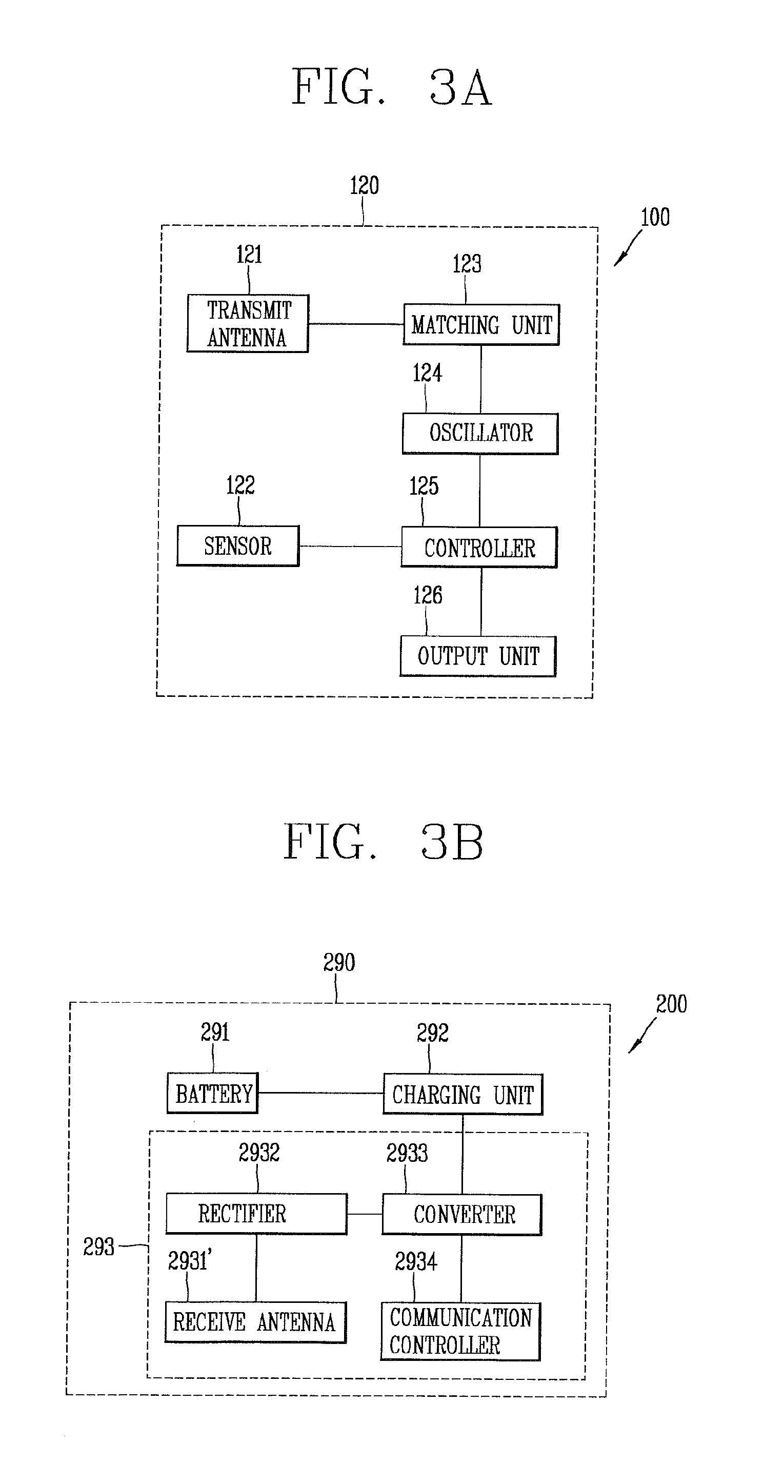
[0112]The pad type charging apparatus can be configured such that an upper surface of its body can be stepped. The electronic device 200 can be placed on a lower stepped portion of the stepped portions of the body. As aforesaid, the electromagnetic induction type charging unit 110 or the magnetic resonance type charging unit 120 can be received within the lower stepped portion of the body so as to be protected from external impact or contact with foreign materials.

[0113]An upper surface of the lower stepped portion can be formed of an insulating material, for example, plastic, to prevent an occurrence of a short due to an electrical conduction with the electronic device. Alternatively, the upper surface thereof can be...

second embodiment

[0133]FIGS. 7A and 7B are perspective views showing still another type of foldable charging apparatus for charging a plurality of electronic devices in accordance with the

[0134]As shown in FIGS. 7A and 7B, a plurality of cover bodies 171 and 172 can be coupled to a main body of the charging apparatus 100 by hinges. Each of the cover bodies 171 and 172 can additionally accommodate therein the aforesaid electromagnetic induction type charging unit 110 or the magnetic resonance type charging unit 120. As the plurality of cover bodies are employed, the number of electronic devices to be charged can be increased.

third embodiment

[0135]FIGS. 8A and 8B are perspective views showing a slide type charging apparatus for charging a plurality of electronic devices in accordance with a

[0136]As shown in FIG. 8A, a charging apparatus 100 for charging a plurality of electronic devices can be a slide type.

[0137]An extendable body 180 can be slidably retracted into one side surface of a main body of the charging apparatus 100. The extendable body 180 can be slid by a user's force or an elastic force to be drawn out as shown in FIG. 8B. A stopper can be formed at one end of the extendable body 180 so as to be obviated from being completely separated from the main body even if the extendable body 180 is pulled out by an excessive force.

[0138]An upper surface of the main body of the charging apparatus 100 can be stepped.

[0139]The aforesaid electromagnetic induction type charging unit 110 or the magnetic resonance type charging unit 120 can be mounted within the main body and the extendable body 180.

[0140]The upper surfaces...


PUM


Abstract

A wireless charging apparatus and system according to an embodiment of the present invention provides a wireless charging service through authentication so as to efficiently control charging rights with respect to a plurality of electronic devices, which desire to receive the wireless charging service using a shared wireless charging apparatus, resulting in allowing a user to get a stable wireless charging service and proposing a new benefit creation model. The wireless charging apparatus according to an embodiment of the present invention includes a wireless communication unit configured to receive authentication result information relating to a target electronic device from a server, and a wireless charging unit configured to wirelessly transmit power to the target electronic device if the authentication result information indicates a successful authentication, wherein the wireless communication unit transmits the authentication result information to the target electronic device if the authentication result information indicates an unsuccessful authentication.

Description

[0001]This application claims the benefit of Korean Patent Application No. 10-2011-0038424, filed on Apr. 25, 2011, which is hereby incorporated by reference for all purposes as if fully set forth herein.BACKGROUND OF THE INVENTION[0002]1. Field of the Invention[0003]This specification relates to an electronic device, and particularly, to a wireless charging apparatus and system.[0004]2. Background of the Invention[0005]As portability is required more and more for various electronic devices belonging to users, importance of battery efficiency is gradually increasing. Accordingly, various approaches to make the battery highly efficient have been introduced. However, further progress in battery charging has not been made in spite of those approaches or attempts for enhancement of the battery efficiency.[0006]Especially, in order to charge different electronic devices, power adaptors suitable for the respective electronic devices should be individually provided, which causes users to f...

Claims


Application Information

Patent Timeline
IPC IPC(8): G05B19/00
CPCG07F15/006H02J7/025H02J7/0044H02J7/0004H02J7/00036H02J7/00047H02J50/80H02J50/90H02J50/12H02J7/00045H02J7/0048
Inventor PARK, JINMOOCHU, INCHANGLEE, JAESUNG
Owner LG ELECTRONICS INC
Why Eureka
Try Eureka