
X-ray source with an immersion lens

a technology of x-ray source and lens, applied in the field of x-ray source, can solve the problems of limiting the resolution of x-ray point projection microscope, and reducing the operating life of the targ

Active Publication Date: 2012-10-25
CARL ZEISS X RAY MICROSCOPY
View PDF14 Cites 58 Cited by
  • Summary
  • Abstract
  • Description
  • Claims
  • Application Information

AI Technical Summary

Benefits of technology

[0011]Note that the target may include: tungsten, tantalum, molybdenum, rhenium, copper and/or compounds that include two or more of these elements. Moreover, a

Problems solved by technology

These x-ray-source sizes may limit the resolution of an x-ray point projection microscope.
Moreover, in these applications there is typically a tradeoff between the x-ray intensity and the operating life of the target or the x-ray intensity and the x-ray beam quality.
Furthermore, as the electron-beam current is increased, the operating life of the target is decreased because the degradation of the location on the target that is bombarded by the electrons is accelerated.

Method used


Image

  • X-ray source with an immersion lens
  • X-ray source with an immersion lens
  • X-ray source with an immersion lens

Examples


Embodiment Construction

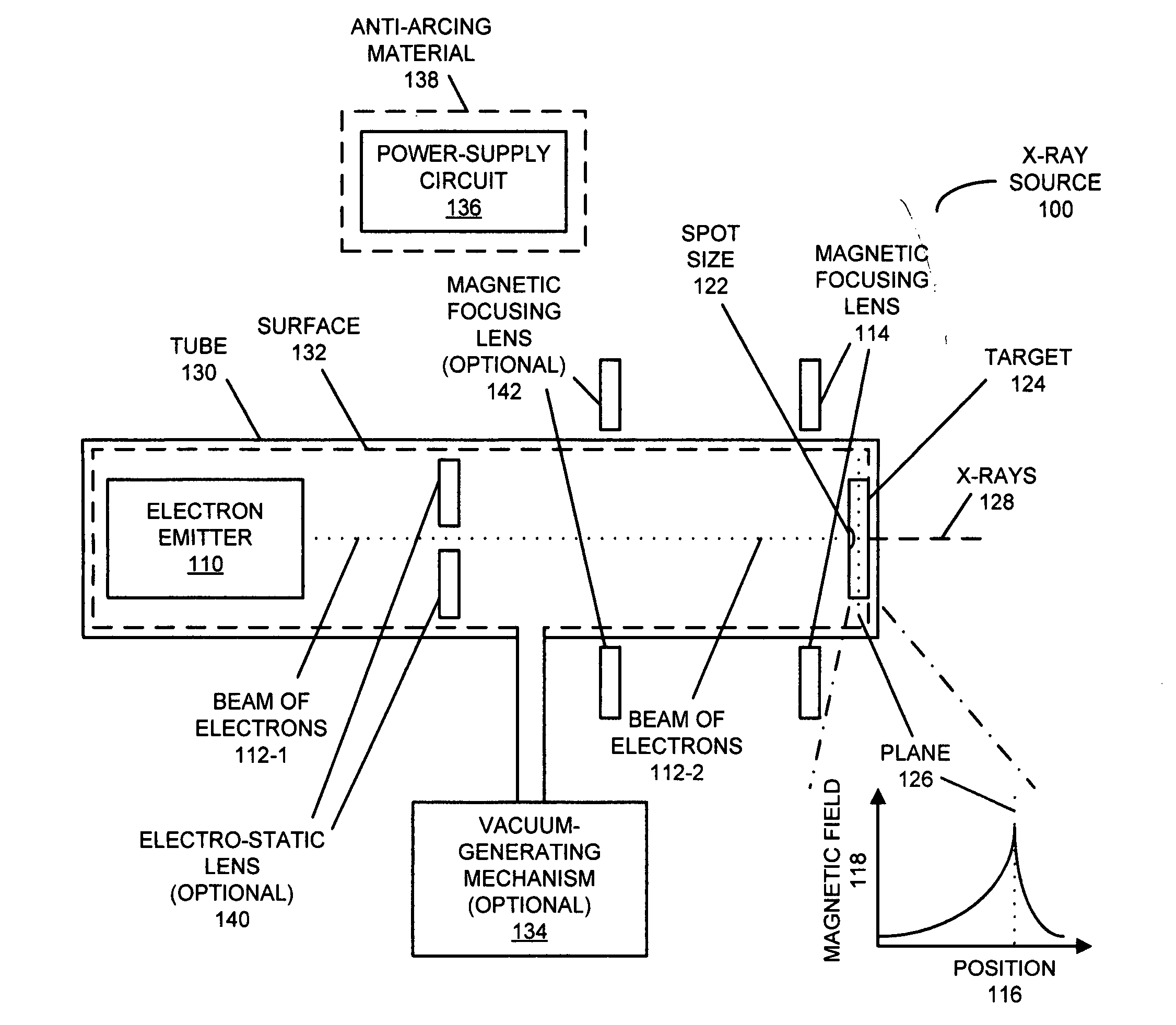
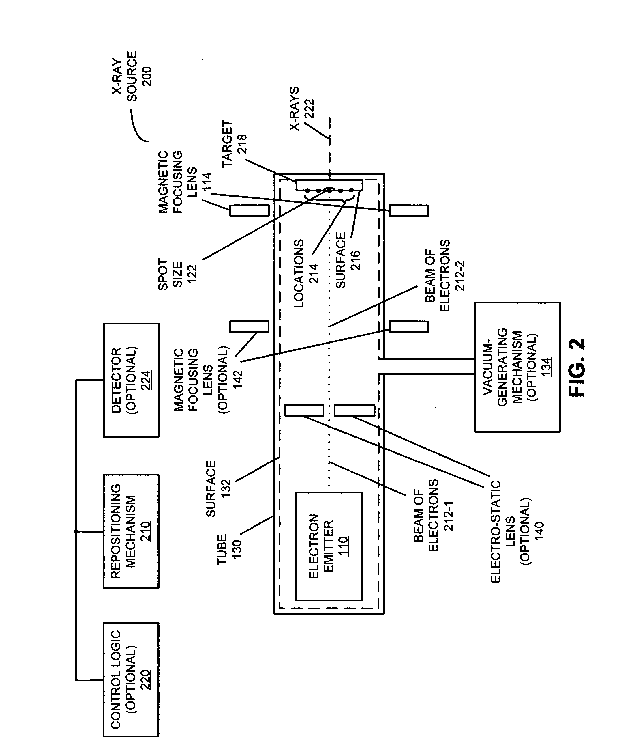
[0031]Embodiments of an x-ray source and associated methods are described. During operation of the x-ray source, an electron source emits a beam of electrons. Moreover, a repositioning mechanism selectively repositions the beam of electrons on a surface of a target based on a feedback parameter, where a location of the beam of electrons on the surface of the target defines a spot size of x-rays output by the x-ray source. In response to receiving the beam of electrons, the target provides a transmission source of the x-rays. Furthermore, a beam-parameter detector provides the feedback parameter based on a physical characteristic associated with the beam of electrons and / or the x-rays output by the x-ray source. This physical characteristic may include: at least a portion of an infrared spectrum or a visible spectrum emitted by the target when it receives the beam of electrons; secondary electrons emitted by the target based on a cross-sectional shape of the beam of electrons; an int...


PUM


Abstract

An x-ray source is described. During operation of the x-ray source, an electron source emits a beam of electrons. This beam of electrons is focused to a spot on a target by a magnetic focusing lens. In particular, the magnetic focusing lens includes an immersion lens in which a peak in a magnitude of an associated magnetic field occurs proximate to a plane of the target. Moreover, in response to receiving the beam of focused electrons, the target provides a transmission source of x-rays.

Description

CROSS REFERENCE TO RELATED APPLICATIONS[0001]This application claims priority under 35 U.S.C. 120 to U.S. Non-provisional patent application Ser. No. 13 / 066,679, entitled “X-ray Source with Selective Repositioning of Electron Beam,” by David L. Adler et al., filed on Apr. 21, 2011, the contents of which are herein incorporated by reference.[0002]This application is also related to U.S. Non-provisional patent application Ser. No. ______, entitled “X-ray Source with High-Temperature Electron Emitter,” by David L. Adler et al., filed on Nov. ______ 2011, and to U.S. Non-provisional patent application Ser. No. ______, entitled “X-ray Source with Increased Operating Life,” by David L. Adler et al., filed on ______, 2011.FIELD OF THE INVENTION[0003]The present disclosure relates generally to an x-ray source and associated methods. More specifically, the present disclosure relates to an x-ray source that includes a magnetic focusing lens with an immersion lens.BACKGROUND[0004]X-rays are wi...

Claims


Application Information

Patent Timeline
IPC IPC(8): H01J35/32H05G1/08
CPCH01J35/08H01J35/14H05G1/52H01J2235/087H01J2235/186H01J35/116H01J35/186H01J35/147H01J35/153
Inventor ADLER, DAVID L.YUN, WENBINGCASE, THOMAS ANTHONY
Owner CARL ZEISS X RAY MICROSCOPY
Learn More