Planetary drive system

Inactive Publication Date: 2012-10-25
GEAR DRIVE ZT
View PDF5 Cites 1 Cited by
  • Summary
  • Abstract
  • Description
  • Claims
  • Application Information

AI Technical Summary

Benefits of technology

[0010]A planetary drive system having an input that is disposed within a gear housing and is connected to a speed control system. A cross connecting shaft is drivingly engaged by the speed co

Problems solved by technology

These systems are complicated and expensive.
A disadvantage of using hydraulic drives and other methods is the attempt to synchronize the two drives when it required that the vehicle travel in a straight line.
Lack of mechanical connection causes drift and constant adjustment to the travel direction is required by the operator.
Other disadvantages of the hydraulic drives are the waste of power due to losses required to circulate the oil.
In addition, internal leakage leads to loss of efficiency.
Further, the hydraulic drives have a tendency to sustain damage when started in very cold temperatures and additionally the motor can sustain damage when the vehicle is moved with the engine turned off.
Additional disadvantages of current systems include that the available torque from the motors is too low to directly drive the transaxle to the wheel and a secondary speed reduction system must be used between the hydraulic motor and the axle.
Unfortunately, the savings offered by the small motor is often offset by the requirement of employing a gear reduction to increase the torque.

Method used


Image

  • Planetary drive system
  • Planetary drive system
  • Planetary drive system

Examples


Embodiment Construction

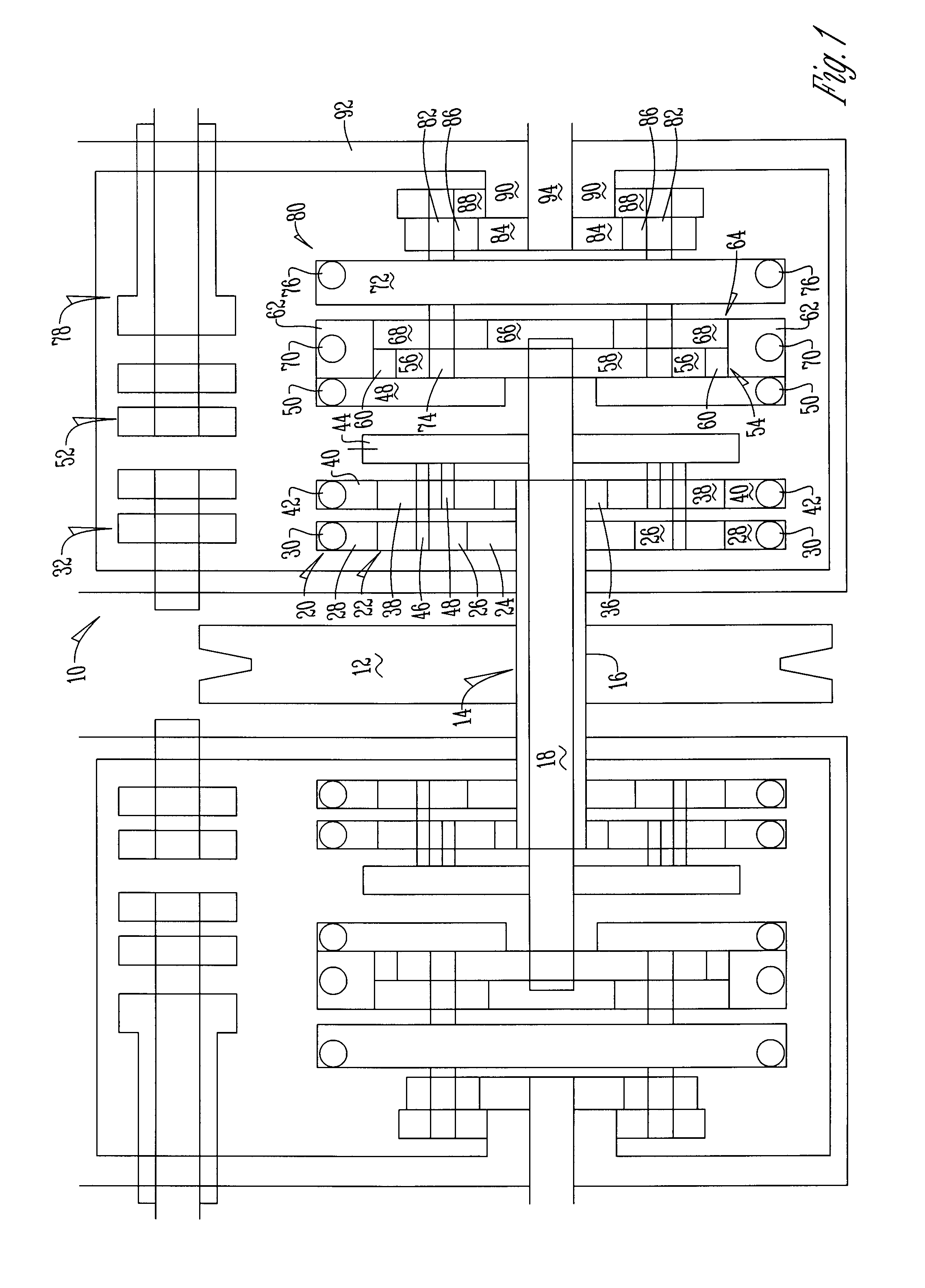
[0016]The figures show components of a gear drive system 10 utilized to drive the wheels of a vehicle such as a lawnmower, skid loader, and the like. The system 10 includes an engine or electric motor (not shown) that provides an input 12 into a transaxle 14. The input 12 is not specific. It can be a pulley, a chain, a gear or a continuously variable drive system. Fixed connections to shafts can be splines or keys or tapers, which ever type suits the application. Snap rings and set screws may also be used. For clarity, these devices are not shown.

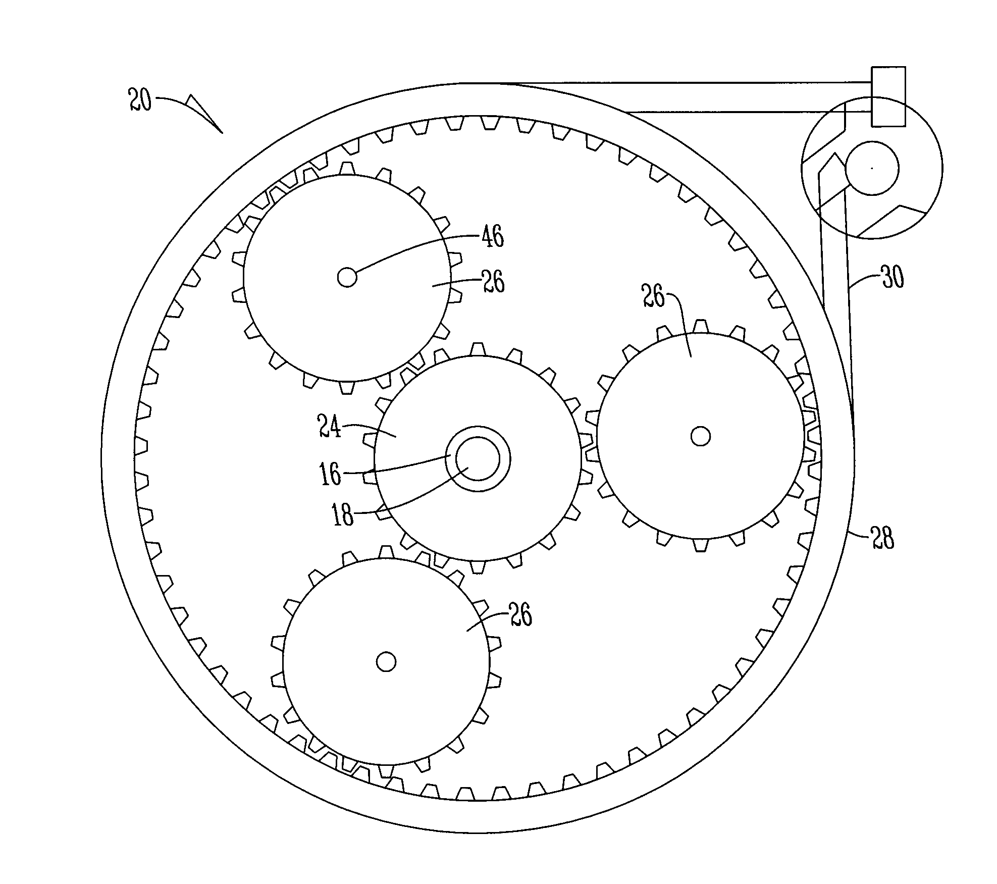
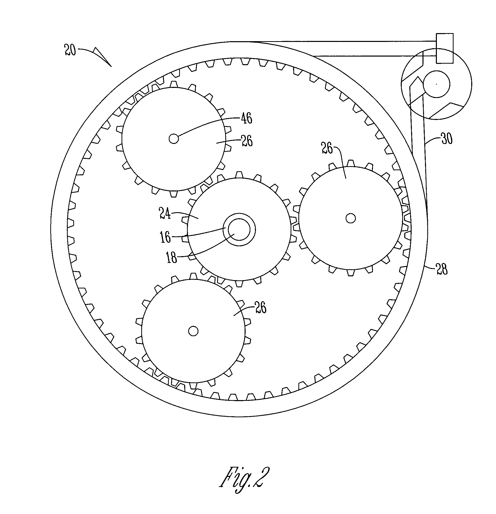
[0017]The input 12 drives and is mounted to the tubular cross shaft 16 that surrounds cross shaft 18 and which drives a speed control gear set 20. The gear set 20 has a first section 22 having a sun gear 24 that meshingly and drivingly engages a planet gear 26 that meshingly engages a ring gear 28. A first clutch element 30 is disposed around the ring gear 28 and is connected to a first actuator 32 such that when the first actuator 32 is ro...


PUM


Abstract

A planetary drive system that has an input and a gear housing that is connected to a speed control system. A cross connecting shaft is drivingly engaged by the speed control system and rotatably connects to a forward and reverse gear set that is drivingly connected to a reduction gear set to provide an output. The speed control system, forward and reverse gear set, and reduction gear set are actuated by band clutch elements that frictionally engage the exterior of ring gears and carriers within the system to control the operation of the planetary drive system.

Description

CROSS REFERENCE TO RELATED APPLICATION[0001]This application claims the benefit of U.S. Provisional Application No. 61 / 478,712 filed Apr. 25, 2011.BACKGROUND OF THE INVENTION[0002]This invention relates to a planetary drive system for a vehicle. Specifically, this invention relates to a transmission used to power vehicles that steer by changing the speed of the wheels on one side of the vehicle relative to the wheels on the other side of the vehicle.[0003]Typically, in lawnmowers, skid loaders and the like have vehicle steering that allows the changing of wheel speed on one side of the vehicle relative to the other and in some instances one side can actually be reversed while the other side travels forward such that the vehicle can execute a zero turn. This is commonly accomplished by using three different differentials. They are often times powered by hydraulic motors or pumps. Specifically, lawnmowers use a pair of hydraulic motors wherein one motor is attached to one side wheel a...

Claims


Application Information

Patent Timeline
IPC IPC(8): F16H57/10F16H57/08
CPCB62D11/12A01D69/06
Inventor WELLS, DAVID
Owner GEAR DRIVE ZT
Why Eureka
Try Eureka